
2.5 Emergency Overcurrent Protection
87
7ST6 Manual
E50417-G1176-C251-A3
2.5
Emergency Overcurrent Protection
2.5.1
General
Whereas the distance protection can only function correctly if the measured voltage
signals are available to the device, the emergency overcurrent protection only requires
the currents.
The emergency overcurrent protection function is activated automatically, and only if
the distance protection is ineffective (emergency operation). Emergency operation su-
persedes in this case the distance protection as a short-circuit protection.
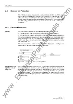
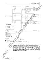
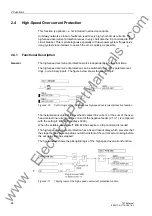
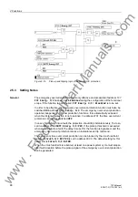
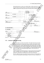
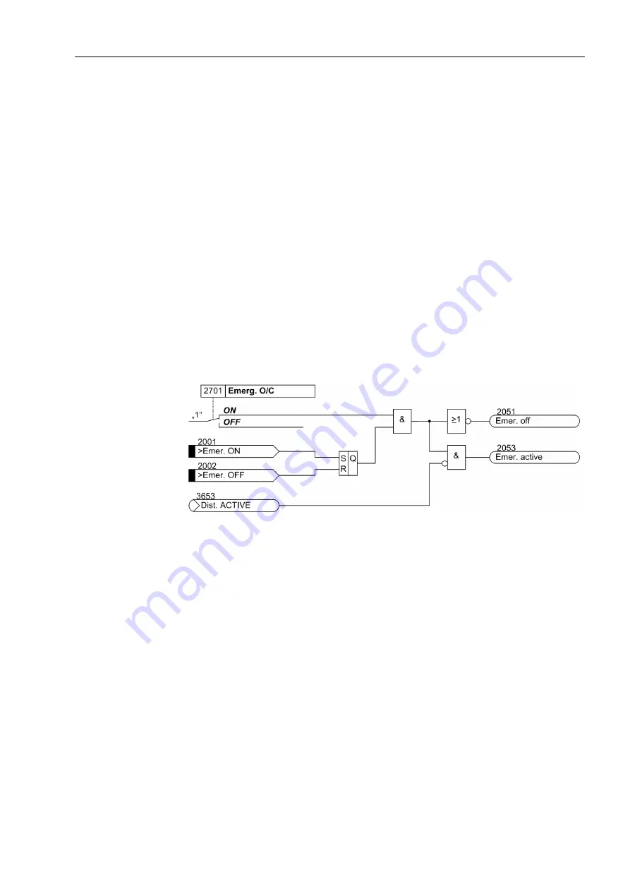
The emergency overcurrent protection is effective if one of the following conditions is
fulfilled (see Figure 2-18):
• Tripping of the voltage transfomer MCB
• Pickup of the internal measuring voltage monitoring, e.g. by a short-circuit or an in-
terruption of the voltage transformer secondary circuit (see also Section
2.16.3„Fuse Failure Monitor“, in Section 2.16), or
• Distance protection is switched off or ineffective.
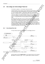
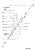
Figure 2-18
Control logic of the emergency overcurrent protection
2.5.2
Functional Description
Emergency Over-
current Protection
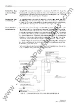
The emergency overcurrent protection has a time overcurrent stage with current-inde-
pendent trip time. Undelayed tripping can be set when the protected line is switched
onto a fault. If the stage is not needed, it can be disabled (in address
2702
).
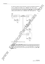
The current of the overhead contact line, or in auto-transformer systems optionally the
summated overhead contact line current and the negative feeder current, are numer-
ically filtered and compared with the setting
I Emerg. O/C
.
Currents above the associated pickup value are detected and signalled. After expiry
of the associated time delay
T Emerg. O/C
a trip command is issued.
The dropout value is approximately 5 % less than the pickup value, but at least 1.8 %
of the rated current, below the pickup value.
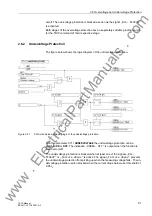
The figure below shows the logic diagram of the emergency overcurrent protection
function.
www
. ElectricalPartManuals
. com