
3.1 Mounting and Connections
229
7ST6 Manual
E50417-G1176-C251-A3
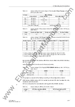
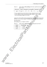
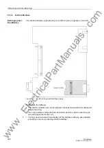
Table 3-21
Exchangeable Interface Modules
The order numbers of the exchange modules can be found in the Appendix in Section
A.1, Accessories.
RS232 Interface
Interface RS232 can be modified to interface RS485 and vice versa (see Figures 3-12
and 3-13).
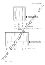
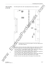
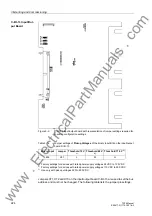
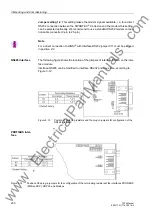
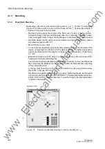
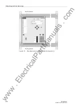
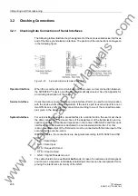
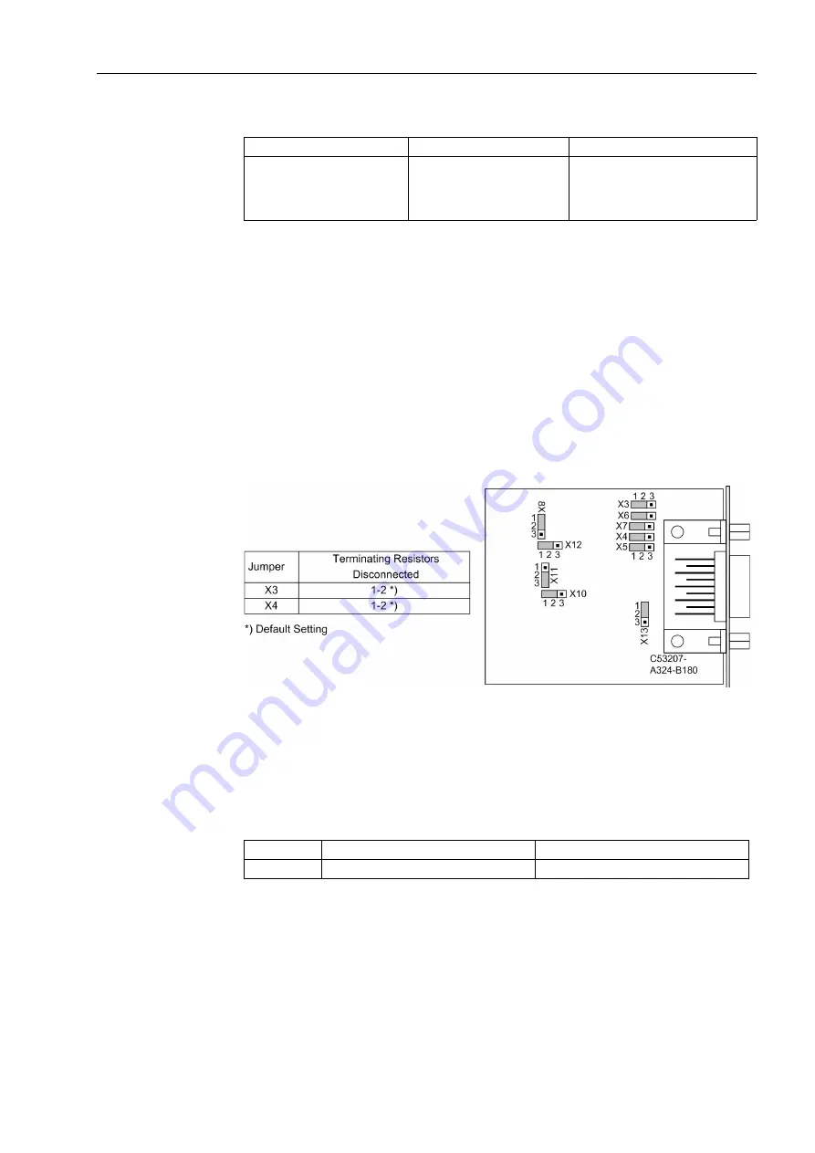
Figure 3-11 shows the PCB of the C-CPU-2 with the layout of the boards.
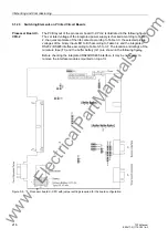
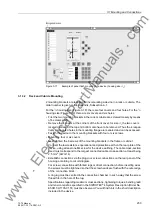
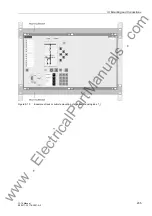
The following figure shows the location of the jumpers of interface RS232 on the inter-
face module.
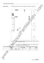
The fibre optics module is controlled via an RS232 interface module at the associated
CPU interface slot. For this application type the jumpers X12 and X13 on the RS232
module are plugged in position 2-3.
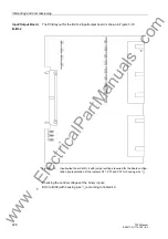
Figure 3-12
Location of the jumpers for configuration of RS232
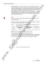
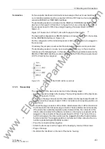
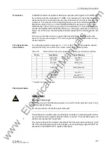
Terminating resistors are not required for RS232. They are disconnected.
With jumper X11 the flow control which is important for modem communication is en-
abled.
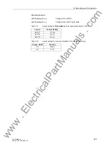
Table 3-22
Jumper setting for
CTS (Flow Control)
on the interface board
1)
Factory Setting
Jumper setting 2-3:
The connection to the modem is usually established with a star
coupler or fibre-optic converter. Therefore the modem control signals according to
RS232 standard DIN 66020 are not available. Modem signals are not required since
communication to SIPROTEC
®
4 devices is always carried out in the half duplex
mode. Please use the connection cable with order number 7XV5100-4.
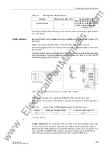
Interface
Mounting Location / Port
Exchange Module
System interface
O
Only interface modules that can
be ordered in our facilities via the
order key (see also Appendix,
Section A.1).
Jumper
/CTS from Interface RS232
/CTS Controlled by /RTS
X11
1-2
2-3
www
. com