

3 Mounting and Commissioning
222
7ST6 Manual
E50417-G1176-C251-A3
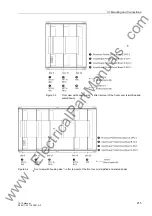
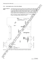
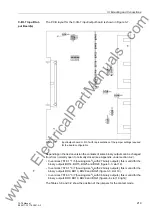
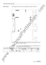
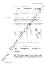
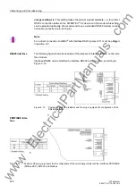
Board C-I/O-12
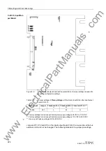
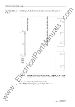
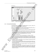
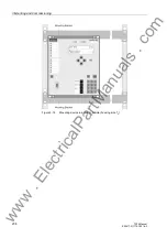
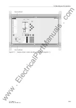
The PCB layout for the C-I/O-12 input/output board is shown in Figure 3-8.
Figure 3-8
C-I/O-12 input/output board with representation of jumper settings required for
checking configuration settings
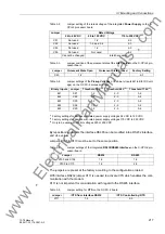
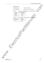
Table 3-13
Jumper setting for the
Contact Mode
of the relays for BO4 and BO5 on the in-
put/output board C-I/O-12 with housing size
1
/
2
Device 7ST61*1/5
Printed Circuit
Board
For
Jumpe
r
Open in Quies-
cent State (NO)
Closed in Quiescent State
(NC)
Factory
Setting
Slot 33
BO4
X41
1-2
2-3
1-2
Slot 33
BO5
X42
1-2
2-3
1-2
www
. ElectricalPartManuals
. com