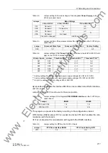

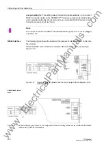

3.1 Mounting and Connections
219
7ST6 Manual
E50417-G1176-C251-A3
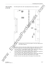
C-I/O-7 Input/Out-
put Board(s)
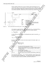
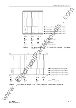
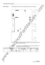
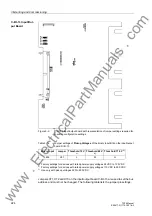
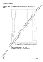
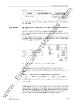
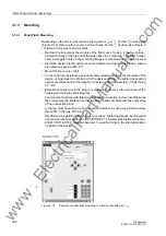
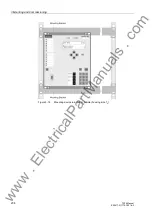
The P.C.B layout for the C-I/O-7 input/output board is shown in Figure 3-7.
Figure 3-7
Input/output board C–I/O-7 with representation of the jumper settings required
for the board configuration
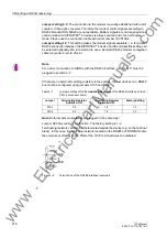
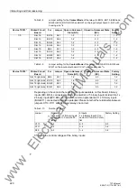
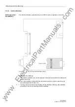
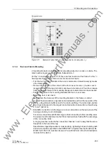
Depending on the device version the contacts of some binary outputs can be changed
from from normally open to normally closed (see Appendix, under section A.2).
• In versions 7ST6 1 * 1/5 (housing size
1
/
2
with 27 binary outputs), this is valid for the
binary outputs BO14, BO15, BO25 and BO26 (figure 3-3, slot 19).
• In versions 7ST6 1 * 3/7 (housing size
1
/
2
with 22 binary outputs), this is valid for the
binary outputs BO9, BO10, BO20 and BO21 (figure 3-3, slot 19).
• In versions 7ST6 3 * 3/7 (housing size
1
/
1
with 36 binary outputs), this is valid for the
binary outputs BO9, BO10, BO20 and BO21 (figure3-4, slot 19 right);
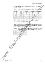
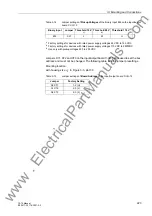
The Tables 3-8 and 3-9 show the position of the jumpers for the contact mode.
www
. ElectricalPartManuals
. com