


Busbar Protection
103
7SS52 V4 Manual
C53000-G1176-C182-3
The 7SS52 V4 is configured to identify an isolator automatically as a line isolator.
If an isolator is configured as line isolator, the feeder bay will only be allocated to a bus
zone if both the corresponding bus isolator and the feeder isolator are closed.
5.1.3
Bus Coupler Variants
Most large busbar configurations are divided into different zones which constitute au-
tonomous subsystems
−
called zones or measuring systems
−
that can be selectively
protected. The subsystems are connected by bus couplers so that the configuration
can assume all required operating states. Depending on the number of current trans-
formers and the type of switching element, a bus coupler can have different design
variants. The bus coupler variants are automatically recognized by the DIGSI Plant
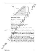
Configuration. The admissible types of bus couplers are shown below.
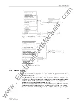
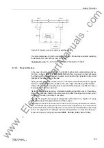
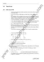
Figure 5-11 Examples of bus coupler variants
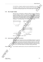
5.1.3.1
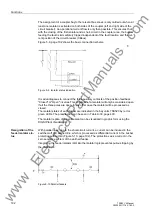
Bus Couplers with One Current Transformer
Bus couplers with circuit breaker and one current transformer (Figure 5-11, page 103)
are the most common variant. The low cost of this economical solution is offset by the
disadvantage of a delayed trip of the faulted subsystem if a fault occurs in the dead
zone with the coupler closed. The ”dead zone” is understood to be the bus zone be-
tween the circuit breaker and the current transformer. With the coupler open, the de-
tection of the circuit breaker status ensures selective tripping without delay.
1-bay coupler
In the 7SS52 V4 protection system, one bay unit is needed for this type of bus coupler.
www
. ElectricalPartManuals
. com