Functions
102
7SS52 V4 Manual
C53000-G1176-C182-3
The assignment of a coupler bay to the relevant bus zones is only carried out when at
least one isolator is activated on both sides of the coupler (left and right side of the
circuit breaker). An operational current flow is only then possible. This ensures that,
with the closing of the first isolator and a short-circuit in the coupler area, the busbar
feeding the fault is immediately tripped independent of the fault location and the cur-
rent position of the circuit breaker (CBaux).
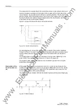
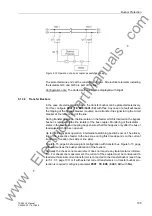
Figure 5-9, page 102 shows the basic connection scheme.
Figure 5-9 Isolator status indication
It is advantageous to connect the three auxiliary contacts of the position feedback
"Closed" or "Open" in series. This ensures that an isolator will only be considered open
if all the three poles are open. In any other case the isolator will be processed as
closed.
The isolator states of each feeder are indicated in the bay units 7SS523 by red or
green LEDs. The preselection can be seen in Table A-30, page 400.
The isolator replica of the entire plant can be visualized in graphic form using the
DIGSI Plant Visualization.
Recognition of the
feeder isolator sta-
tus
With parallel lines, due to the short-circuit current, a current can be induced in the
switched-off and earthed line, which is processed as differential current in the busbar
protection without Q9.(Figure 5-10, page 102). The protection sees a current in the
zero sequence system of the earthed feeder.
Integrating the feeder isolator (Q9) into the isolator logic prevents spurious tripping by
the 7SS52 V4.
Figure 5-10 Parallel feeders
www
. ElectricalPartManuals
. com


