Functions
94
7SS52 V4 Manual
C53000-G1176-C182-3
The measuring circuit of the 7SS52 V4 is characterized by the following features:
•
Basic principle:
Monitoring the sum of the currents as the tripping quantity
•
Measures taken to guard against the disturbing influences due to current-transform-
er saturation:
−
Stabilization (against large through currents)
−
Separate evaluation of each half-wave (particularly effective against DC
components)
•
Measures taken to obtain short tripping times:
Separate evaluation of the current transformer currents during the first milliseconds
after the occurrence of a fault (anticipating the current transformer saturation).
5.1.1.2
Algorithm with Instantaneous Values
Stabilization
The stabilization reduces the influence on the measurement of transformation inaccu-
racies in the various feeders to such a degree that spurious behaviour of the protection
system is prevented. The differential protection forms both the vectorial sum of the CT
secondary currents, which acts in the operating sense, and the arithmetic sum of
those quantities, which has a restraining effect.
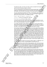
The stabilizing (restraint) current thus obtained is additionally smoothed by the soft-
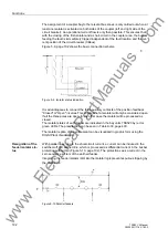
ware (Figure 5-2, page 94) to ensure stability even in cases of extreme saturation.
Figure 5-2 Formation of the stabilizing (restraint) current
Characteristic
The operating conditions for the busbar protection vary considerably between one
plant and the other, as do the setup and the switching possibilities of the individual sta-
tions. For instance, the range between the lowest and the highest currents to be ex-
pected in case of a short-circuit is different for each plant. Another important factor are
the data and burdens of the CTs available for connecting the protection system. Final-
ly, the treatment of the starpoint in the high-voltage system has some importance for
the design and setting of the protection. For all these reasons, the busbar protection
system has to offer a high degree of flexibility.
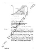
The standard characteristic is determined by the two settable parameters ”Stabiliza-
tion factor k” and ”Differential current limit Id
>
".
www
. ElectricalPartManuals
. com

