Functions
6-118
7SA522 Manual
C53000-G1176-C119-2
6.6.1.3
Directional Blocking Scheme
Principle
In the case of the blocking scheme, the transmission channel is used to send a block
signal from one line end to the other. The signal transmission may be started immedi-
ately after fault inception (jump detector) and is stopped as soon as the earth fault pro-
tection recognizes a fault in the forward direction, alternatively the signal is only sent
when the earth fault protection detects the fault in the reverse direction. On the other
hand the signal will be maintained if the fault is in reverse direction. If the signal is sent
with jump detections (i. e.
is routed in parallel with
), only a short delay to allow for signal transmission is required before the
directional E/F trips. Tripping is possible with this scheme even if no signal is received
from the opposite line end. It is therefore mainly used for long lines when the signal
must be transmitted across the protected feeder by means of power line carrier (PLC)
and the attenuation of the transmitted signal at the fault location may be so severe that
reception at the other line cannot necessarily be guaranteed.
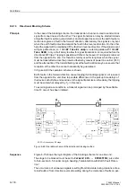
In Figure 6-69 the operation scheme is shown.
Earth faults in the forward direction cause tripping if a blocking signal is not received
from the opposite line end. Due to possible differences in the pick up time delays of
the devices at both line ends and due to the signal transmission time delay, the tripping
must be somewhat delayed by T
V
in this case.
To avoid signal race conditions, a transmit signal can be prolonged by the settable
time T
S
once it has been initiated.
Figure 6-69 Operation scheme of the directional blocking method
Sequence
Figure 6-70 shows the logic diagram of the blocking scheme for one line end.
The stage to be blocked must be set to
)RUZDUG
(
,',5(&7,21
); also refer
to Sub-section 6.5.2 under margin heading „Teleprotection with Earth Fault Protec-
tion“.
The occurrence of erroneous signals resulting from transients during clearance of ex-
ternal faults or from direction reversal resulting during the clearance of faults on par-
A
B
EF
FD
trip
rec.
&
d
dt
40 ms
T
S
&
≥
1
transm.
(u,i)
3I0 Min
Telep.
(A)
T
V
EF
FD
trip
rec.
&
d
dt
40 ms
T
S
&
≥
1
transm.
(u,i)
(B)
T
V
E/F.
forwd.
E/F.
forwd.
3I0 Min
Telep.
EF/FD = Pickup by any E/F stage
Summary of Contents for siprotec 7SA522
Page 20: ...7SA522 Manual C53000 G1176 C119 2 ...
Page 64: ...7SA522 Manual C53000 G1176 C119 2 ...
Page 89: ...SIPROTEC 4 Devices 4 25 7SA522 Manual C53000 G1176 C119 2 Figure 4 20 CFC Logic example ...
Page 408: ...7SA522 Manual C53000 G1176 C119 2 ...
Page 456: ...7SA522 Manual C53000 G1176 C119 2 ...
Page 516: ...7SA522 Manual C53000 G1176 C119 2 ...
Page 620: ...Appendix B 48 ...


