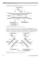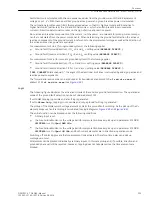
[u2-u1-einpoliger-ausfall-020828-ho, 1, en_US]
If a fault occurs in the voltage transformer secondary system, the following rules apply to the Two-phase
Failure:
[u2-u1-zweipoliger-ausfall-020828-ho, 1, en_US]
In case of a failure of one or two phases of the primary system, the current also shows a negative sequence
system of 0.5 or 1. Consequently, the voltage monitoring does not respond since no voltage transformer fault
can be present. In order to avoid occurrence of an overfunctioning of the measuring voltage failure detection
due to inaccuracy, the function is blocked below a minimum threshold of the positive sequence systems of
voltage (V
1
< 0.1 V
Nom
) and current (
Ι
1
< 0.1
Ι
Nom
).
If the absolute values of the positive or negative sequence voltage are below 20 % of V
Nom
/
√
3, the 1-pole or 2-
pole FFM detection is blocked.
Three-phase Failures in Voltage Transformer Circuits
A 3-phase failure in the voltage transformer secondary system cannot be detected via the positive- and nega-
tive- sequence system as described above. The monitoring of the progress of current and voltage over time is
required here. If a voltage dip to almost zero occurs (or if the voltage is zero), and the current remains
unchanged, a 3-phase failure in the voltage transformer secondary system can be concluded. The jump detec-
tion is used for this purpose. The sensitivity of the jump detection for current can be increased via parameter
FFM Idiff (3ph)
.
Broken Wire Monitoring of Voltage Transformer Circuits
Requirements
This function is only available in device version “World” or “Chinese” Ordering Information Pos. 10 = B or K), as
it is only used in certain regions.
Furthermore, the measurement of all three phase-to-ground voltages is a requirement.
If only two phase-to-phase voltages were measured, it would not be possible to evaluate two of the required
criteria.
Task
The “Broken Wire” monitoring function monitors the voltage transformer circuits of the secondary system with
regard to failure. One distinguishes between single-phase, two-phase and three-phase failures.
Mode of Operation / Logic
All three phase-to-ground voltages, the displacement voltage and the three phase currents are measured. The
required values are calculated for the respective criteria and eventually a decision is made. The resulting alarm
message may be delayed. A blocking of the protection functions is however not effected. This is done by the
measuring voltage failure detection.
The “Broken Wire” monitoring is also active during a fault. The function may be enabled or disabled.
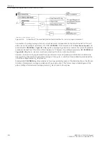
The following logic diagram shows how “Broken Wire” monitoring functions.
2.12.1.7
Functions
2.12 Monitoring Functions
SIPROTEC 4, 7SJ62/64, Manual
189
C53000-G1140-C207-8, Edition 08.2016
Summary of Contents for SIPROTEC 4
Page 8: ...8 SIPROTEC 4 7SJ62 64 Manual C53000 G1140 C207 8 Edition 08 2016 ...
Page 18: ...18 SIPROTEC 4 7SJ62 64 Manual C53000 G1140 C207 8 Edition 08 2016 ...
Page 30: ...30 SIPROTEC 4 7SJ62 64 Manual C53000 G1140 C207 8 Edition 08 2016 ...
Page 540: ...540 SIPROTEC 4 7SJ62 64 Manual C53000 G1140 C207 8 Edition 08 2016 ...
Page 594: ...594 SIPROTEC 4 7SJ62 64 Manual C53000 G1140 C207 8 Edition 08 2016 ...
Page 720: ...720 SIPROTEC 4 7SJ62 64 Manual C53000 G1140 C207 8 Edition 08 2016 ...


