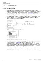
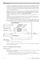

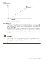
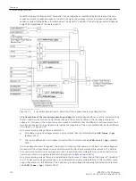

A circuit-breaker position logic is incorporated in the device (
). Depending on the type of auxiliary
contact( s) provided by the circuit breaker and the method in which these are connected to the device, there
are several alternatives of implementing this logic.
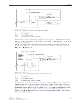
In most cases, it is sufficient to send the status of the circuit breaker from the CB's auxiliary contacts over a
binary input to the device. The NO auxiliary contact of the circuit breaker is connected to a binary input which
must be routed to
>52a 3p Closed
(no. 379).
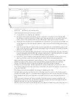
If the series connection of the poles' auxiliary NC contacts is available, the corresponding binary input is routed
to
>52b 3p Open
(no. 380).
The output signals of the circuit-breaker position logic can be processed by the individual protection and
supplementary functions. The output signals are blocked if the signals transmitted from the circuit breaker are
not plausible: for example, the circuit breaker cannot be open and closed at the same time.
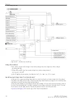
The evaluation of the measured quantities is according to the local conditions of the measuring points (see
Section
at margin heading “Circuit-Breaker Status”).
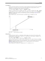
The phase currents are available as measured quantities. A flowing current excludes that the circuit breaker is
open (exception: a short circuit between current transformer and circuit breaker). If the circuit breaker is
closed, it may, however, still occur that no current is flowing. The decisive setting for the evaluation of the
measured quantities is
PoleOpenCurrent
(address 1130) for the presence of the currents.
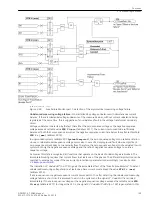
In 7SD80 the position of the circuit-breaker poles detected by a device is also transmitted to the remote end
device. Thus the circuit-breaker positions at both ends are known.
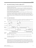
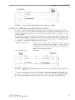
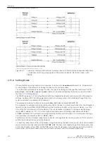
[lo-ls-stellung-2010112, 1, en_US]
Figure 2-62
Circuit-breaker position logic
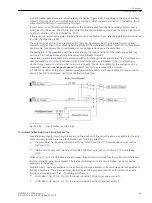
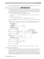
For Automatic Reclosing and Circuit-Breaker Test
Separate binary inputs comprising information on the position of the circuit breaker are available for the auto-
matic reclosing function and the circuit-breaker test. This is important for
•
the plausibility check before automatic reclosing (refer to Section
2.11 Automatic Reclosure Function
•
the trip circuit check with the help of the TRIP-CLOSE test cycle (refer to Section
).
When using 1
1
/
2
or 2 circuit breakers in each feeder, the automatic reclosure function and the circuit-breaker
test are referred to one circuit breaker. The feedback information of this circuit breaker can be connected
separately to the device.
Separate binary inputs are available to this end which should be treated in the same way and configured addi-
tionally if necessary. These have a similar significance as the inputs described above for protection applica-
tions and are marked with “CB1 ...” to distinguish them, i.e.:
•
>52a Bkr1 3p Cl
(no. 410) for the series connection of the NO auxiliary contacts,
•
>52b Bkr1 3p Op
(no. 411) for the series connection of the NC auxiliary contacts.
Functions
2.12 Circuit Breaker Test
SIPROTEC 4, 7SD80, Manual
145
E50417-G1100-C474-A2, Edition 02.2018
Summary of Contents for SIPROTEC 4 7SD80
Page 8: ...8 SIPROTEC 4 7SD80 Manual E50417 G1100 C474 A2 Edition 02 2018 ...
Page 10: ...10 SIPROTEC 4 7SD80 Manual E50417 G1100 C474 A2 Edition 02 2018 ...
Page 18: ...18 SIPROTEC 4 7SD80 Manual E50417 G1100 C474 A2 Edition 02 2018 ...
Page 248: ...248 SIPROTEC 4 7SD80 Manual E50417 G1100 C474 A2 Edition 02 2018 ...
Page 298: ...298 SIPROTEC 4 7SD80 Manual E50417 G1100 C474 A2 Edition 02 2018 ...
Page 312: ...312 SIPROTEC 4 7SD80 Manual E50417 G1100 C474 A2 Edition 02 2018 ...
Page 322: ...322 SIPROTEC 4 7SD80 Manual E50417 G1100 C474 A2 Edition 02 2018 ...
Page 400: ...400 SIPROTEC 4 7SD80 Manual E50417 G1100 C474 A2 Edition 02 2018 ...
Page 402: ...402 SIPROTEC 4 7SD80 Manual E50417 G1100 C474 A2 Edition 02 2018 ...


