


Connection
6.6 X3/X4 (PROFIBUS DP / 24 V DC)
SIPLUS HCS3200
32
Operating Instructions, 07/2014, A5E31278506C/002
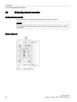
6.6
X3/X4 (PROFIBUS DP / 24 V DC)
PROFIBUS DP
To enable communication between SIMATIC S7 / SIMOTION and the heating controller,
connect PROFIBUS DP to the CPU module through plug connection X3 / X4.
A bus terminating resistor is required for terminating the bus.
If the bus connector is located at the start or the end of a bus segment, the terminating
resistor must be connected. The bus terminating resistors are already integrated into the
Siemens bus terminators (6GK1 905-0DA10).
Make sure that stations with an activated terminating resistor are always supplied with power
during startup and operation.
Unused connectors must be fitted with a cover in the plant.
24 V DC power supply
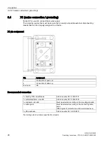
The 24 V infeed is supplied via pins 1/2 or 3/4 of the PROFIBUS connector. The user must
ensure that the maximum current-carrying capacity of the connector of 10 A is not exceeded.
Pin assignment X3 / X4
Connection sockets X3 and X4 have the same pin assignment. Both connections are
internally linked 1:1. The signals can be transmitted further using daisy chaining.
Table 6- 2
6-pin connection for 24 V DC and PROFIBUS DP
Pin
Assignment
1
Supply voltage 1: 24 V DC, for heating controller
2
Reference potential 1, for heating controller
3
Reference potential 2
4
Supply voltage 2: 24 V DC
Q
PROFIBUS DP, A signal
B
PROFIBUS DP, B signal
Summary of Contents for SIPLUS HCS3200
Page 1: ......
Page 2: ......
Page 24: ...Mounting 5 3 Final work SIPLUS HCS3200 24 Operating Instructions 07 2014 A5E31278506C 002 ...
Page 74: ......


