SIPART DR19
C73000-B7474-C140-06
59
Quick Reference
Configuring
1)
If S21 = 4, values are standardized on dA to dE.
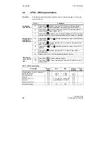
3.3
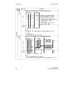
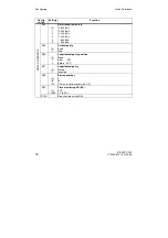
StrS - Configuring switches
Switches (software), which define how the instrument is configured.
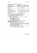
Parameter
Param.-
name
Min
Max
Factory
setting
Eng.
unit
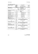
Setpoint start of scale
SA
-10 % to 110 %
of dA, dE
-5.0
Setpoint full scale
SE
105.0
Setpoint ramp time
tS
oFF/0.100
9984
oFF
min
Ratio factor - start
Ratio factor - end
vA
vE
0.000
0.000
9.999
9.999
0.000
1.000
1
1
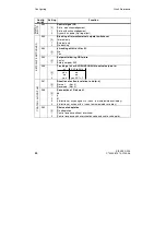
Safety manipulated value
Split range left (Y1<Y2)
Split range right
YS
Y1
Y2
-10.0
0.0
0.0
110.0
100.0
100.0
0.0
50.0
50.0
%
%
%
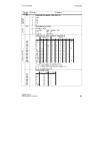
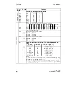
Linearizer
output value
L-1 (-10%) to L11 (110%)
are equidistant
input vertices
L-1
L0
L1
L2
L3
etc.
up to
L11
-10.0
-10.0
-10.0
-10.0
-10.0
"
-10.0
110.0
110.0
110.0
110.0
110.0
"
110.0
-10.0
0.0
10.0
20.0
30.0
etc.
up to
110.0
%
1)
%
1)
%
1)
%
1)
%
1)
"
%
1)
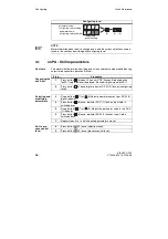
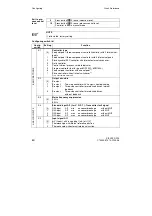
Step
Procedure
1
Press button
(6) about 5 sec until "PS" flashes. Release button -
"onPA" (selection level) displayed. Blocked if digital signal bLPS=1.
2
Press button
(8) several times until "StrS" is displayed (selection
level). Blocked if digital signal bLS=1.
3
Press button
(9) about 3 sec until digital indicator SP-W (2) flashes
(configuring level). Controller now blocked and last value of y retained.
4
Using buttons
(7) or
(8). Select parameter names in the SP-W (2)
digital indicator.
5
Press button
(6) once, indicator PV-X (1) flashes, adjustment
buttons 7, 8 operate on PV-X.
6
Using pushbuttons
(7) or
(8) Modify parameter values in the PV-X
(1) indicator.
7
Press button
(6) once, indicator SP-W (2) flashes, input field is
switched back.
8
Repeat steps 4 to 7 until all desired parameters are set.
Contents
Accessing the
StrS list
Select and
modify config-
uring
switches
Summary of Contents for SIPART DR19
Page 2: ......
Page 6: ...SIPART DR19 6 C73000 B7474 C140 06 Übersicht Kurzanleitung ...
Page 50: ...SIPART DR19 50 C73000 B7474 C140 06 Overview Quick Reference ...
Page 93: ......


