Electrical installation
4.10 Other connections
Converter cabinet units
142
Operating Instructions, 07/2016, A5E03347396A
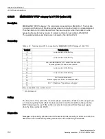
4.10.14
Insulation monitor (option L87)
Description
In non-grounded systems (IT systems), the insulation monitor checks the entire electrically-
connected circuit for insulation faults. The insulation resistance as well as all the insulation
faults from the mains supply to the motor in the cabinet are detected. Two response values
(between 1 kΩ and 10 MΩ) can be set. If a response value in undershot, an alarm is output
to the terminal. A system fault is output via the signaling relay system.
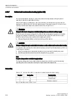
When the cabinet unit is delivered, the plant configuration (one or several loads in one
electrically-connected network) and the protection philosophy (immediate shutdown in the
event of an insulation fault or restricted continued motion) can vary. This means that the
signaling relays of the insulation monitor must be integrated by the customer in the fault and
warning sequence.
Safety information
Note
Number of insulation monitors
Only one insulation monitor can be used within the same electrically-connected network.
Note
Removing the connection bracket for the interference-suppression capacitor
When the insulation monitor is used, the connection clip to the interference suppression
capacitor must be removed (see "Electrical installation / Removing the connection clip to the
interference suppression capacitor with operation from an ungrounded line supply (IT
system)").
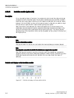
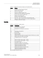
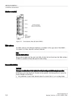
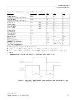
Controls and displays on the insulation monitor
Figure 4-27 Controls and displays on the insulation monitor
Summary of Contents for SINAMICS G150
Page 1: ......
Page 2: ......
Page 8: ...Foreword Converter cabinet units 8 Operating Instructions 07 2016 A5E03347396A ...
Page 18: ...Table of contents Converter cabinet units 18 Operating Instructions 07 2016 A5E03347396A ...
Page 679: ......
Page 680: ......

