


Functions
7.1 Overview of the inverter functions
Inverter with CU240B-2 and CU240E-2 Control Units
156
Operating Instructions, 07/2010, FW 4.3.2, A5E02299792B AA
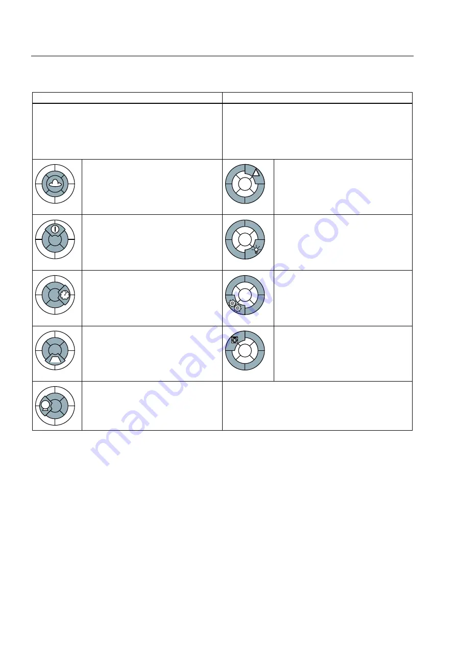
Functions relevant to all applications
Functions required in special applications only
The functions that you require in your application are
provided in the center of the function overview above.
In the quick commissioning, the parameters of these
functions are assigned an appropriate basic setting, so that
in many cases the motor can be operated without having to
assign any other parameters.
The functions whose parameters you only need to adapt
when actually required are located at the outer edge of the
upper function overview.
Inverter control is responsible for all of the
other inverter functions. Among other
things, it defines how the inverter responds
to external control signals.
Inverter control (Page 157)
The production functions avoid overloads
and operating states that could cause
damage to the motor, inverter and driven
load. The motor temperature monitoring,
for example, is set here.
Protection functions (Page 175)
The command source defines where the
control signals are received from to switch
on the motor, e.g. via digital inputs or a
fieldbus.
Command sources (Page 158)
The status messages provide digital and
analog signals at the outputs of the Control
Unit or via the fieldbus. Examples include
the actual speed of the motor or fault
message issued by the inverter.
Status messages (Page 186)
The setpoint source defines how the speed
setpoint for the motor is specified, e.g. via
an analog input or a fieldbus.
Setpoint sources (Page 159)
The technological functions allow you to
activate a motor holding brake or
implement a higher-level pressure or
temperature control using the technology
controller, for example.
Technological functions (Page 187)
The setpoint processing uses a ramp-
function generator to prevent speed steps
occurring and to limit the speed to a
permissible maximum value.
Setpoint calculation (Page 166)
The safety functions are used in
applications that must fulfill special
requirements placed on the functional
safety.
Safe Torque Off (STO) safety function
0
The motor closed-loop control ensures that
the motor speed or torque follows its
setpoint.
Motor control (Page 168)