


Functions
7.10 Safe Torque Off (STO) safety function
Inverter with CU240B-2 and CU240E-2 Control Units
214
Operating Instructions, 07/2010, FW 4.3.2, A5E02299792B AA
7.10
Safe Torque Off (STO) safety function
These operating instructions describe the commissioning of the STO safety function when it
is controlled via a fail-safe digital input.
You will find a detailed description of all safety functions and control using PROFIsafe in the
Safety Integrated Function Manual, see Section Overview of documentation (Page 13).
Note
We strongly recommend commissioning the safety functions exclusively with the STARTER
commissioning tool.
7.10.1
Prerequisite for STO use
In order to use the STO safety function, your machine should have already performed a risk
assessment (e.g. in compliance with EN ISO 1050, "Safety of machinery - Risk assessment -
Part 1: Principles"). The risk assessment must confirm that the inverter is permitted for use in
accordance with SIL 2 or PL d.
7.10.2
Permitted sensors
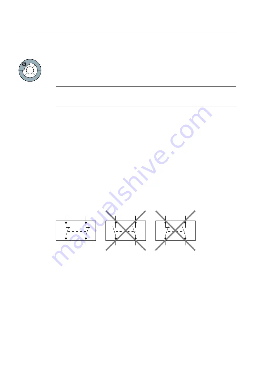
The fail-safe inputs of the inverter are designed for connecting sensors with two NC
contacts.
It is not possible to directly connect sensors with two NO contacts and antivalent contacts (1
NO contact and 1 NC contact).
Figure 7-19 Sensors that can be connected to the fail-safe inputs
The fail-safe digital inputs are configured for both directly connecting safety sensors, e.g.
emergency stop control devices or light curtains, as well as for connecting pre-processing
safety relays, e.g. fail-safe controls.
On the following pages, you will find examples of interconnecting the fail-safe digital input
from "Basic safety", in accordance with PL d to EN 13849-1 and SIL2 to IEC 61508. You can
find further examples and information in the Safety Integrated Function Manual.