+\VWHUHVLV
$FWXDOSRVLWLRQRID[LV
;
VWDUW
6ZLWFKLQJVWDWHRIWLPHEDVHGFDP
2XWSXWFDP
GRHVQRWVZLWFK
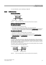
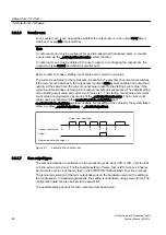
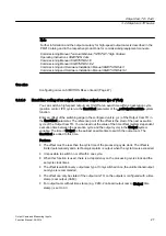
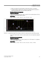
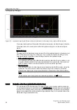
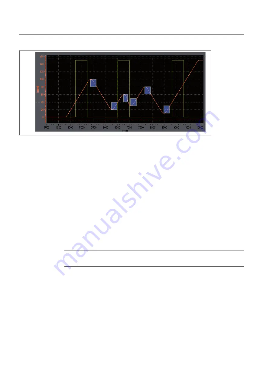
Figure 3-16 Hysteresis range (height of blue sections) and behavior of a time-based cam, positive effective direction
Time-based cam switches off only after ON duration has expired, not after change of direction.
Time-based cam with a start position within the hysteresis range is not output (see figure
above).
Hysteresis range
The upper limit of the hysteresis range is set at 25% of the working range for a linear axis, and
25 % of the rotary axis range for a rotary axis. If you violate this maximum setting, an error
message is issued. In practice, a lower setting is used for the hysteresis range.
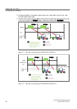
● Path-controlled output cam
The hysteresis becomes active after direction reversal is detected. If only a positive or only
a negative effective direction has been parameterized for an output cam, the output cam
does not switch off after a reversal of direction until it has left the hysteresis.
● Time-based cam
The switching behavior of a time-based cam is determined by the ON duration, not by the
hysteresis. This means that an entered hysteresis range has no influence on the ON
duration of an output cam. It only has an influence on the switch-on time (start position).
Note
If a time-based cam's start position lies within the hysteresis, it is not output.
3.2.2.3
Derivative-action times (activation/deactivation time)
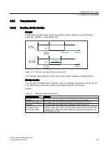
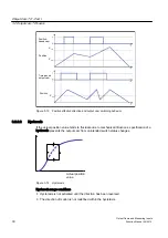
To compensate for the switching times of digital outputs and connected switching elements,
or of propagation delays, it is possible to specify actuation times. Actuation times are calculated
from the sum of all delay times and can be specified separately for activation and deactivation
edges as an actuation time at the activation edge (activation time) or an actuation time at the
deactivation edge (deactivation time).
Output Cam TO - Part I
3.2 Output cam TO basics
Output Cams and Measuring Inputs
32
Function Manual, 04/2014

