


SIMOTICS A-1FV5/1PV5 synchronous/induction motors
Operating Instructions, 03/2014, 610.45002.40
35
Connection
6
6.1
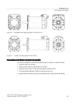
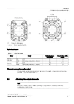
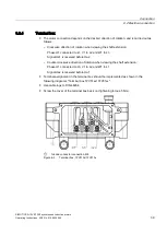
Mechanical connection of water cooling system
The inlet and outlet holes for the cooling water supply are located on the NDE in the bearing
shield.
1.
Make sure that the cooling water fulfills the required cooling water specification, see the
chapter titled "Cooling".
2.
Make sure that the appropriate volume of cooling water is available, see the rating plate
(type plate).
3.
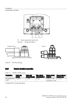
Attach the cooling water pipes to the cooling water connections. You can connect the inlet
and outlet as required.
4.
Ensure that the maximum permissible operating pressure does not exceed 2.5 bar.
5.
Ensure that the cooling water connections and the cooling water pipes are not subject to
continuous forces.
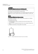
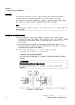
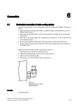
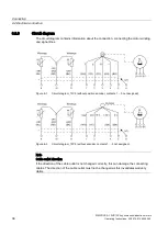
Adjusting the outlet direction of the cooling water connection:
1.
Remove the union nut from the adjusting bracket
2.
Rotate the adjusting bracket to the required output direction
3.
Manually fix the adjusting bracket
4.
Tighten the union nut to 32 Nm using a torque wrench
See also


