Description
3.4 Design
SIMOTICS A-1FV5/1PV5 synchronous/induction motors
Operating Instructions, 03/2014, 610.45002.40
19
3.4.4
Ambient conditions
The motors are designed for ambient temperatures from -40 °C to +70 °C and installation
altitudes up to 2500 m above sea level. In the case of different ambient conditions, contact
the manufacturer.
3.4.5
Cooling
Water cooling
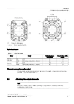
The motor can only be operated in a closed coolant circuit with a cooling unit. The motor is
connected to the cooling circuit using two hose connections with an outer diameter of 18 mm
at the NDE bearing shield of the motor. On motors with angled hose connections, after
loosening the locknuts they can be adjusted in both directions (preferred direction clockwise;
max. 1 revolution). After adjusting the position, the coolant connections must be fixed by
tightening the union nuts.
The inlet and outlet connections can be selected as required.
Table 3- 4
Technical data of the water cooling
Coolant
Water/anti-freeze mixture, 50/50 %
Cooling water connection
Hose connection with an outer diameter of 18
Female thread in the bearing shield Pg 13.5 /8 deep
Cooling water flow
16 l/min
Lower values will result in a derating
Max. pressure at inlet
max. 2.5 bar
Pressure loss between inlet and
outlet
< 0.2 bar for minimum cooling water flow with
1PV513/1FV513
< 0.4 bar for minimum cooling water flow with 1FV516
Min. cooling water inlet temperature T
cool
> T
ambient
– 5 K
at T
ambient
<60 °C; T
coolmin
> -40 °C
Maximum cooling water inlet
temperature, without derating
≤
55 °C,
higher values will result in derating
As coolant, only a water/anti-freeze mixture in a ratio of 50 % / 50 % is permissible. Glycol is
recommended as antifreeze. When you select a different anti-freeze, a minimum steady-
state temperature of -40 °C must be observed. Different anti-freeze agents should not be
mixed.
A filter (100 µm) must be installed in the inlet pipe to protect the motor against pollution.
Additional protection for the motor must be provided by means of a pressure relief valve
installed downstream from the filter.
If a throttle is needed to restrict the flow, it is best to install it downstream of the motor. It is
not permissible to install the throttle directly in front of the inlet because the effects of
cavitation may damage the motor.


