4 ASCII protocol communication
CP340/CP341/CP440/CP441 Communication and Programming
Entry-ID: 88867653, V1.0, 02/2014
25
S
ie
m
e
n
s
A
G
2014
A
ll r
ig
h
ts
r
e
s
e
rv
e
d
Fig. 41: Invoke FB10 SEND_440 from OB1
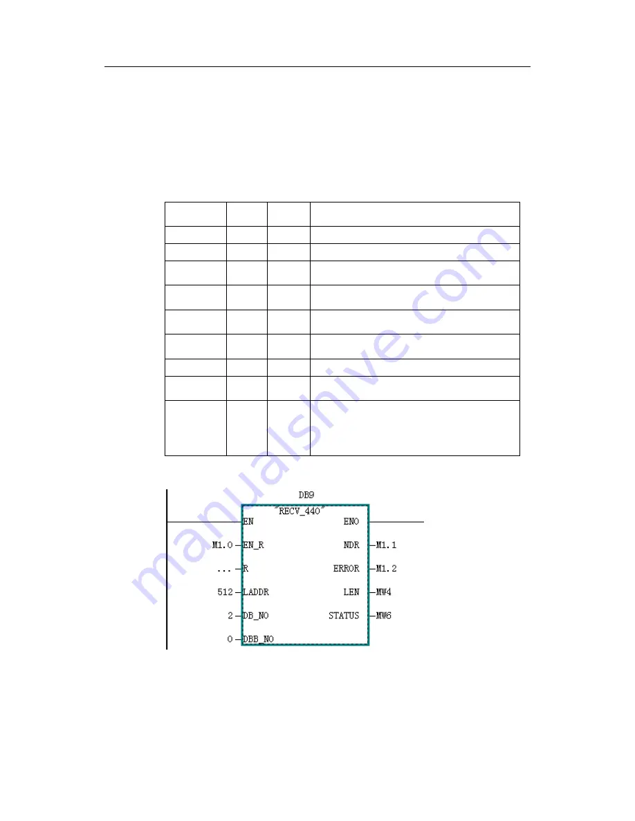
4. Invoke receive function block FB9 RECV_440 from the same folder in the library
and distribute instance data block DB9 to it, and set LADDR as input start logic
address 512 in hardware configuration.
5. Create receive data block DB2
6. Invoke receive function block
The parameters of the receive function block FB9 RECV_CP440 are set as in the
table below:
Name
Type
Data
format
comments
EN_R
Input
BOOL
Enable receive bit, which is M1.0 in this example.
R
Input
BOOL
Cancel communication and give up receive
LADDR
Input
INT
Module start logic address in hardware
configuration, which is 512 in this example
DB_NO
Input
INT
Receive Data block number, which is 2(DB2) in
this example
DBB_NO
Input
INT
Start address of Receive Data, which is
0(DB2.DBB0) in this example
NDR
Output
BOOL
Receive complete bit, which is TRUE if Receive
completes and has no error
ERROR
Output
BOOL
error bit, which is TRUE if receive has error
LEN
Output
INT
Length (in byte) of receive data, which is not 0 only
in the current cycle when data are received.
STATUS
Output
WORD
status word indicating error code. If ERROR = 1,
this status word includes error information, and
user may check implication of the information code
online or obtain the related instruction from CP440
manual.
Table 8: Parameter definition of FB9 RECV_440
Fig. 42: Invoke FB9 RECV_440 from OB1


