background image

4 Functional Mechanisms of the Application

4.4 Visualization

Monitoring of 24 V load circuits
Entry-ID: 61450284,    V1.1,    05/2014

23

C

o

p

y

ri

g

h

t

S

ie

m

e

n

s

A

G

2

0

1

4

A

ll

ri

g

h

ts

re

s

e

rv

e

d

4.4

Visualization

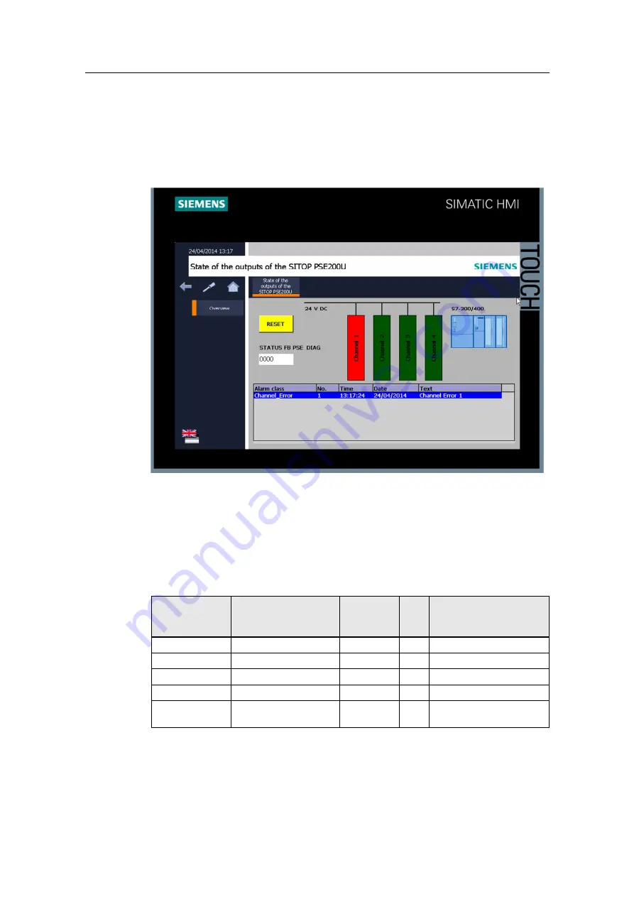
The “State of the outputs of the SITOP PSE200U” screen displays the variables of
the HMI interface at the SIMATIC Panel. The variables of the HMI interface are
linked with WinCC basic objects and elements.

Figure 4-4

4.4.1

Displaying the states

To display the states of output OUT 1 to OUT 4 as well as the state of the
PSE_DIAG (FB50) block on the SIMATIC Panel, the following variables of the HMI
interface in the “State of the outputs of the SITOP PSE200U” screen are linked with
WinCC basic objects and elements.

Table 4-7

WinCC Basic

object /

element

Variable

Data type

Bit

Description

Text field

CHANNEL_STATE

BYTE

0

Channel 1

Text field

CHANNEL_STATE

BYTE

1

Channel 2

Text field

CHANNEL_STATE

BYTE

2

Channel 3

Text field

CHANNEL_STATE

BYTE

3

Channel 4

I/O field

STATUS_SAVE

WORD

-

Status of the PSE_DIAG
(FB50) block

Summary of Contents for SIMATIC S7-300 CPU Data: CPU 315-T-2 DP

Page 1: ...http support automation siemens com WW view en 61450284 Application description 05 2014 Monitoring of 24 V load circuits S7 300 CPU SITOP PSE200U with single channel signaling SIMATIC Panel ...

Page 2: ...haftungsgesetz in case of intent gross negligence or injury of life body or health guarantee for the quality of a product fraudulent concealment of a deficiency or breach of a condition which goes to the root of the contract wesentliche Vertragspflichten The damages for a breach of a substantial contractual obligation are however limited to the foreseeable damage typical for the type of contract e...

Page 3: ... Messages FB10 block and calling the ALARM_D message blocks 33 5 2 2 ALARM_D message block 34 5 2 3 Inputs and outputs of the ALARM_D message block 35 5 2 4 Editing the PLC alarms in the Alarm class editor 38 5 2 5 Display PLC alarm at the SIMATIC Panel 39 5 3 Changing the I O addresses 40 6 Installation 41 6 1 Hardware configuration 41 6 1 1 Structure 41 6 1 2 Overview of the I O addresses 42 6 1...

Page 4: ...4 V load circuits Entry ID 61450284 V1 1 05 2014 4 Siemens AG 2014 All rights reserved 8 4 1 Overload of the motor 64 8 4 2 Short circuit at the lighting 65 8 4 3 Error of the PSE_DIAG FB50 block 66 9 Links Literature 67 10 History 67 ...

Page 5: ... All rights reserved 1 Task Overview of the automation task Figure 1 1 Visualization Control S7 CPU Operator panel Display of the load circuits Display of the messages Power supply and load circuits Power Supply 24V DC PSE 200U Load 4 Load 3 Load 2 Load 1 OUT 1 4 Status S Digital Input serial coding ...

Page 6: ...verload or a short circuit occurs in a load circuit In the case of an overload or short circuit the appropriate outputs OUT 1 to OUT 4 are automatically switched off The state output S of the PSE200U module supplies a signal that serially codes the state of the outputs OUT 1 to OUT 4 The following tasks must be solved in order for the status of the individual channels to be evaluated by the SIMATI...

Page 7: ...al The information available from the evaluation is displayed as message on a SIMATIC Panel We will show you how the PSE_DIAG FB50 block is integrated in the user program of the S7 CPU how the states of outputs OUT 1 to OUT 4 of the PSE200U module are visualized on a SIMATIC Panel TP900 Comfort Panel a message procedure control messages PLC alarms Schematic layout The figure below shows a schemati...

Page 8: ...Via a digital output the remote reset input RST of the PSE200U module is controlled by the S7 CPU 5 SIMATIC S7 300 400 CPU In the user program of the S7 CPU the signal of the status output S is evaluated to monitor the states of the load circuits connected at outputs OUT 1 to OUT 4 of the PSE200U module The S7 CPU detects output OUT 1 of the PSE200U module is switched off e g due to an overload at...

Page 9: ...ified and adjusted by the user Advantages The application on hand offers you the following advantages Detecting overload or short circuit in individual 24 V load circuits reliably even for long and thin lines or creeping short circuits and switches the 24 V load circuits to zero current Avoiding plant down times by maintaining the 24 V supply of the remaining consumers Sequential switching of the ...

Page 10: ...1 1 2 3 4 PSE_DIAG DATA The following table describes the process Table 2 3 No Action 1 The PSE_DIAG FB50 block reads the signal of the state output S of the PSE200U module via its IMPULSE input and evaluates it 2 At its CHANNEL_STATE output the PSE_DIAG FB50 block indicates the state of outputs OUT 1 to OUT 4 of the PSE200U module 3 The status information indicated at the CHANNEL_STATE output is ...

Page 11: ...lity Monitoring of 24 V load circuits Entry ID 61450284 V1 1 05 2014 11 Copyright Siemens AG 2014 All rights reserved Visualization on the SIMATIC Panel The screens of the SIMATIC Panel are shown below Table 2 4 Designation Note Start screen Overview ...

Page 12: ...2 2 Description of the core functionality Monitoring of 24 V load circuits Entry ID 61450284 V1 1 05 2014 12 Copyright Siemens AG 2014 All rights reserved Designation Note State of the outputs of the SITOP PSE200U ...

Page 13: ... 1 6GK7343 1EX30 0XE0 Using an S7 CPU with integrated PROFINET interface does not require an Industrial Ethernet CP Digital input module Digital output module SM323 DI8 DO8 24V 1 6ES7323 1BH01 0AA0 Alternatively you can use another digital input module or digital output module TP900 Comfort Panel 1 6AV2124 0JC01 0AX0 Standard software components Table 2 6 Component Qty Order number Note STEP 7 Pro...

Page 14: ...14 14 Copyright Siemens AG 2014 All rights reserved Downloads of the application The following table includes all downloads of the application Table 2 7 Component Note 61450284_SITOP_Appl_S7 300_400_CODE_v11 zip This zip file contains the STEP 7 project 61450284_PSE_DIAG_Applikation_S7 300_DOKU_en pdf This document ...

Page 15: ...ring in a plant The message system in WinCC V12 SP1 processes various alarm methods of the controller and the SIMATIC Panel For the S7 300 CPUs only the control messages PLC alarms are used Control messages PLC alarms are configured in STEP 7 These event related messages are assigned to one respective block FB They are generated in the program editor In the message editor you assign message texts ...

Page 16: ...the following 5 functions User program of the S7 CPU Signal evaluation with the PSE_DIAG FB50 block HMI interface Visualization Message generation with the Messages block FB10 4 1 User program of the S7 CPU The following figure shows the structure of the user program in the S7 CPU Overview Figure 4 1 Initialization Startup OB 100 Analyzing the state of the PSE200U module HMI interface Cyclic inter...

Page 17: ...OMPLETE RESTART After starting the S7 CPU all parameters are reset static variables in the instance data block outputs of the PSE_DIAG FB50 block FB50 PSE_DIAG The block originates from the SITOP_Library_V12_S7 300_S7 400 library The block evaluates the signal of the state output S of the PSE200U module and determines the state of output OUT 1 to OUT 4 of the PSE200U module DB50 iDB_PSE_DIAG Insta...

Page 18: ... output OUT 1 to OUT 4 2 The status information is saved in data block DATA DB2 3 The saved states are read by the SIMATIC Panel TP900 Comfort Panel Depending on the state a PLC alarm is generated and displayed at the SIMATIC Panel 4 The Messages block FB10 calls the ALARM_D message block internally to send PLC alarms regarding the state of outputs OUT 1 to OUT 4 of the PSE200U module to the SIMAT...

Page 19: ...TUS ERROR IMPULSE COM_RST BOOL BOOL BYTE WORD BOOL BOOL BOOL DB50 iDB_DIAG Inputs The following table shows the assignment of the inputs of the PSE_DIAG FB50 block Table 4 3 Input Data type Variable Description IMPULSE BOOL I4 0 Input via which the signal of the state output S is read The address of the input is available in the device configuration of STEP 7 V12 SP1 see chapter 6 1 2 COM_RST BOOL...

Page 20: ...UT 1 to OUT 4 of the PSE200U module is displayed at the CHANNEL_STATE output 0 Evaluation of the signal of the state output S running BUSY BOOL DB2 DBX0 3 1 PSE_DIAG FB50 block is active 0 If at the same time DONE 1 data from the CHANNEL_STATE output can be adopted ERROR BOOL DB2 DBX0 4 Error display 1 error 0 no error CHANNEL_STATE BYTE DB2 DBB1 State of outputs OUT 1 to OUT 4 of the PSE200U modu...

Page 21: ... relevant Bit 5 DB2 DBX1 5 Not relevant Bit 6 DB2 DBX1 6 Not relevant Bit 7 DB2 DBX1 7 Not relevant STATUS output The STATUS output is used for fault diagnosis if the signal of the state output S could not be evaluated successfully The value of the STATUS output is saved in data block DATA DB2 DBW2 and displayed at the SIMATIC Panel If block PSE_DIAG FB50 supplies an error the Error FB PSE_DIAG me...

Page 22: ... DB2 see Table_4_6 These variables are integrated into WinCC V12 SP1 and form the HMI interface Table 4 6 Variable Data type Address Description HMI_RESET BOOL DB2 DBX0 1 Controls the remote reset input RST of the PSE200U module ERROR_MESSAGE BOOL DB2 DBX0 5 Error of the PSE_DIAG FB50 block CHANNEL_STATE BYTE DB2 DBB1 Bit 0 State OUT 1 Bit 1 State OUT 2 Bit 2 State OUT 3 Bit 3 State OUT 4 Bit 4 to...

Page 23: ...e 4 4 4 4 1 Displaying the states To display the states of output OUT 1 to OUT 4 as well as the state of the PSE_DIAG FB50 block on the SIMATIC Panel the following variables of the HMI interface in the State of the outputs of the SITOP PSE200U screen are linked with WinCC basic objects and elements Table 4 7 WinCC Basic object element Variable Data type Bit Description Text field CHANNEL_STATE BYT...

Page 24: ...d 0 Automatic disable can be reset 0 Output manually disabled 0 Output defective internal fuse has tripped 0 Device over temperature 0 Status of the PSE_DIAG FB50 block The STATUS_SAVE variable contains the state of the PSE_DIAG FB50 block and is assigned to an I O field 4 4 2 Controls the remote reset input RST of the PSE200U module The HMI_RESET variable is assigned to the RESET button This enab...

Page 25: ... deactivated EV_ID4 Channel Error 4 AlarmClass deactivated The messages need not be acknowledged As soon as the outputs OUT 1 to OUT 4 of the PSE200U module go back to state 1 the message goes automatically and is no longer displayed in the alarm view Status of the PSE_DIAG FB50 block When the PSE_DIAG FB50 block displays an error at its ERROR output the control message PLC alarm on the status of ...

Page 26: ...k FB10 The Messages FB10 block has the task to send 5 PLC alarms to the SIMATIC Panel Figure 4 5 shows the call of the Messages FB10 block in the user program of the S7 300 400 CPU The Messages FB10 block is called at cyclic intervals in OB1 Figure 4 5 FB10 Messages EV_ID2 EV_ID3 C_Alarm_s C_Alarm_s DB10 iDB_Messages EN EV_ID1 EV_ID4 BOOL C_Alarm_s C_Alarm_s EV_ID5 SIG_OUT1 SIG_OUT2 SIG_OUT3 SIG_O...

Page 27: ... 16 6000_00001 Message number ID of PLC alarm 1 EV_ID2 C_Alarm_s DW 16 6000_00002 Message number ID of PLC alarm 2 EV_ID3 C_Alarm_s DW 16 6000_00003 Message number ID of PLC alarm 3 EV_ID4 C_Alarm_s DW 16 6000_00004 Message number ID of PLC alarm 4 EV_ID5 C_Alarm_s DW 16 6000_00005 Message number ID of PLC alarm 5 SIG_OUT1 BOOL DB2 DBX1 0 Signal that triggers PLC alarm 1 1 PLC alarm 1 is triggered...

Page 28: ...erved Input Data type Variable Value Description SIG_OUT4 BOOL DB2 DBX1 3 Signal that triggers PLC alarm 4 1 PLC alarm 4 is triggered state OUT 4 0 0 PLC alarm 1 is not triggered state OUT 4 1 SIG_ERR_PSEDIAG BOOL DB2 DBX0 5 Signal that triggers PLC alarm 5 1 PLC alarm 5 is triggered PSE_DIAG FB50 block is executed with error 0 PLC alarm 5 is not triggered PSE_DIAG FB50 block is executed without e...

Page 29: ...ARM_D EN SIG ID EV_ID CMP_ID SD TRUE W 16 EEEE DW 16 0000_0003 SD SIG_OUT3 EV_ID3 ALARM_D EN SIG ID EV_ID CMP_ID SD TRUE W 16 EEEE DW 16 0000_0004 SD SIG_OUT4 EV_ID4 ALARM_D EN SIG ID EV_ID CMP_ID SD TRUE W 16 EEEE DW 16 0000_0005 SD SIG_ERR_PSEDIAG EV_ID5 Error FB PSE_DIAG SIG_OUT1 1 SIG_OUT2 1 SIG_OUT3 1 SIG_OUT4 1 SIG_ERR_PSEDIAG 1 The Messages block calls the ALARM_D instruction internally For...

Page 30: ...ssages FB10 iDB_Messages DB10 Error Channel 1 EV_ID2 60000002 Messages FB10 iDB_Messages DB10 Error Channel 2 EV_ID3 60000003 Messages FB10 iDB_Messages DB10 Error Channel 3 EV_ID4 60000004 Messages FB10 iDB_Messages DB10 Error Channel 4 EV_ID5 60000005 Messages FB10 iDB_Messages DB10 Error FB PSE_DIAG When calling the ALARM_D message block in Messages FB10 block the ID of PLC alarm is automatical...

Page 31: ...lowing alarm class is created without acknowledgement Table 5 1 Name Display name Acknowledgement AlarmClass Channel_Error_S7 300 deactivated This alarm class is assigned to the configured control message PLC alarm The control messages PLC alarms of alarm class AlarmClass are displayed in the alarm view of the Overview S7 300 400 screen To create an alarm class please proceed as follows Table 5 2 ...

Page 32: ...ick an empty field in the Alarm class editor and select the context menu Insert new alarm class 3 Assign a unique name for the new alarm class in the Name column The name assigned here is language neutral 4 Assign a display name in the Display name column This name can be translated 5 In the Acknowledgement column you specify whether the messages of this class require acknowledgement or not ...

Page 33: ...M_D message blocks The PLC alarms are created in the Messages FB10 block The table below describes how to create five PLC alarms Filling the block interface of the Messages FB10 block Calling the message block Table 5 3 No Action Remarks 1 In the block interface of the Messages FB10 block you declare five variables of data type C_Alarm_s as input e g EV_ID1 EV_ID2 EV_ID3 EV_ID4 EV_ID5 Note For eac...

Page 34: ...SEDIAG The signals triggering the messages are read via this input 3 For each PLC alarm you call an ALARM_D message block in the Messages FB10 block The ALARM_D message block is located in the Task Card Instructions in pallet Extended instructions Alarming see chapter 5 2 2 4 Assign the inputs and outputs of the five ALARM_D message blocks see chapter 5 2 3 5 2 2 ALARM_D message block Figure 5 1 s...

Page 35: ...s triggered The message is pending until the ALARM_D message block is called with SIG 0 ID Input WORD W 16 EEEE Data channel for the messages EV_ID Input C_ALARM_S WORD Message number CMP_ID Input DWORD ID for identification of the subsystem to which the appropriate message is assigned SD Input ANY Associated value RET_VAL Output INT Error information 5 2 3 Inputs and outputs of the ALARM_D messag...

Page 36: ...sage block signal which triggers the fifth PLC alarm Message number Assign the data type C_Alarm_s variable to the EV_ID input of the ALARM_D message block previously declared as input in the block interface of the Messages FB10 block The following table shows which variable is assigned to the EV_ID input of the ALARM_D messages block Table 5 6 Variable Data type Description EV_ID1 C_Alarm_s Varia...

Page 37: ...ck DW 16 0000_0005 DWORD Value at the CMP_ID input of the fifth ALARM_D message block Associated value In this application example the associated value W 0000 is defined at all five ALARM_D message blocks The associated value W 0000 is saved in the static variable SD of the Messages FB10 block and assigned to the SD input of the ALARM_D message block Error information The following table shows in ...

Page 38: ... alarms please proceed as follows Table 5 9 No Action 1 In the project navigation you click on the arrow on the left side of the PLC_2 CPU 315 2 PN DP device to display the objects and actions for the device Double click on the PLC alarms object The Alarm class editor is opened and displayed in the work area 2 In the Alarm class editor you click on the PLC alarms tab In the Message text column you...

Page 39: ...essage requires acknowledgement or not In this example the Acknowledgement option is deactivated Therefore the messages do not require acknowledgement 5 2 5 Display PLC alarm at the SIMATIC Panel An alarm view is required to display the configured PLC alarms at the SIMATIC Panel In this example the alarm view is located in the State of the outputs of the SITOP PSE200U screen To display the message...

Page 40: ...verview of the I O addresses used in the application Table 5 10 No Action 1 Open the STEP 7 project of the application see chapter 6 3 In the project navigation you click on the arrow on the left side of the PLC_2 CPU 315 2 PN DP device to display the objects and actions for the device Double click on the Device configuration object The hardware and network editor is opened 2 In the Device view ta...

Page 41: ...ure that the polarity is correct 3 Connect the motor with the OUT 1 output of the PSE200U module and the 0V of the power supply Load circuit 1 which is monitored 4 Connect the lighting with the OUT 2 output of the PSE200U module and the 0V of the power supply Load circuit 2 which is monitored 5 Connect the status output S of the PSE200U module with the DI input I4 0 Connect the remote reset input ...

Page 42: ...utput S State of OUT 1 to OUT 4 DI DO Q8 4 Remote reset input RST Reset PSE200U Module Q8 0 Display State OUT 1 Q8 1 Display State OUT 2 Q8 2 Display State OUT 3 Q8 3 Display State OUT 4 6 1 3 Overview of IP addresses The following table gives you an overview of the IP addresses used For each device you can use any IP address in the same subnet Table 6 3 Device IP address CPU 315 2 PN DP 172 16 43...

Page 43: ...n software consists of a project with the following content device configuration user program for the S7 CPU configuration and settings of the SIMATIC Panel The project is available as a zip file on the HTML page from which you downloaded this document Unzip the file 61450284_SITOP_Appl_S7 300_400_CODE_v10 zip into a separate directory The project is then automatically unzipped with all respective...

Page 44: ...t as that of the S7 CPU and of the SIMATIC Panel The figure below shows the network settings to which you have to change the PG PC Table 7 1 No Action Remarks 1 Open the Internet Protocol TCP IP Properties by selecting Start Control Panel Network and Internet Network and Sharing Center Change adapter settings Local Area Connection Select the option field Use following IP address and assign the IP ...

Page 45: ...ess of the SIMATIC Panel as shown in Table 6 3 via which the project is downloaded to the CPU Table 7 2 No Action 1 At the SIMATIC Panel open the Control Panel 2 Double click on the Network and Dial up Connections icon The available network adapter is displayed 3 Open the PN_X1 entry The PN_X1 Settings dialog is opened 4 Go to the IP Address tab Activate Specify an IP address to specify the addres...

Page 46: ...the IP address of SIMATIC S7 300 CPU Before the STEP 7 project can be downloaded to the SIMATIC S7 300 CPU you have to change the IP address of the PROFINET interface as shown in Table 6 3 via which the project is downloaded to the SIMATIC S7 300 CPU Table 7 3 No Action 1 From the online menu you choose the Accessible devices command The Accessible devices dialog is opened ...

Page 47: ...lect the interface type PN IE Depending on the selection only those interfaces of the PG PC are displayed in the PG PC interface drop down list which match the selected interface type Select the desired interface of the PG PC from the PG PC interface drop down list e g an Industrial Ethernet card Since the accessible nodes at the selected interface of the PG PC are displayed in a list Select the S...

Page 48: ... Click on the arrow icon on the left side of the SIMATIC S7 300 CPU in the project navigation to display the Online diagnostics function Double click on the Online diagnostics function The diagnostics and online function of the SIMATIC S7 300 CPU is opened 4 In the diagnostics and online function you assign IP address and subnet mask in Functions according to the figure below Click on the Assign I...

Page 49: ...eserved 7 2 Commissioning 7 2 1 Transferring the project to the SIMATIC Panel Proceed according to the following instruction to transfer the project to the SIMATIC Panel Table 7 4 No Action 1 At the SIMATIC Panel set the transfer mode 2 In the Project tree right click on the SIMATIC Panel HMI_2 TP900 Comfort Select the Compile Software rebuild all menu ...

Page 50: ...tton to transfer the project to the SIMATIC Panel The Extended download to device dialog box or the Load preview dialog box opens automatically 4 The Extended download to device dialog box opens automatically only if the access path from the PG PC to the SIMATIC Panel has to be reset Make the following settings Type of the PG PC interface PN IE PG PC interface Network card of the PG PC Select the ...

Page 51: ...ioning Monitoring of 24 V load circuits Entry ID 61450284 V1 1 05 2014 51 Copyright Siemens AG 2014 All rights reserved No Action 5 In the Load preview dialog box activate the Overwrite All action and click on the Load button to start loading ...

Page 52: ...7 CPU proceed according to the following instruction Table 7 5 No Action 1 In the Project tree select the S7 300 CPU PLC_2 CPU 315 2 PN DP In the toolbar you click on the Compile button 2 In the Project tree select the S7 300 CPU PLC_2 CPU 315 2 PN DP In the toolbar you click on the Download to device button to download project to the SIMATIC S7 300 CPU The Extended download to device or Load prev...

Page 53: ... device dialog box opens automatically only if the access path from the PG PC to the SIMATIC S7 300 CPU has to be reset Make the following settings Type of the PG PC interface PN IE PG PC interface network card of the PG PC Select the S7 300 CPU from the Compatible devices in target subnet list and click on the Load button 4 In the Load preview dialog box click on the Load button to start loading ...

Page 54: ...d click on the Finish button to terminate loading 7 3 Using the application with STEP 7 WinCC V13 Unzip the file 61450284_SITOP_Appl_S7 300_400_CODE_v11 zip into a separate directory The project is then automatically unzipped with all respective subdirectories In STEP 7 WinCC V13 you open the project established with STEP 7 WinCC V12 SP1 Upd4 The message shown in Figure 7 1 appears automatically C...

Page 55: ...right Siemens AG 2014 All rights reserved Confirm the following message with OK In STEP 7 WinCC V13 the upgraded project is created and saved with a new name Figure 7 2 Execute the Edit Compile menu for each device in the project to finish the upgrade Figure 7 3 You can use and edit the project in STEP 7 WinCC V13 when you have finished the upgrade ...

Page 56: ...Monitoring of 24 V load circuits Entry ID 61450284 V1 1 05 2014 56 Copyright Siemens AG 2014 All rights reserved In the network view of the hardware and network editor select the SIMATIC Panel and choose the Change device version menu The Change device dialog box opens Figure 7 4 ...

Page 57: ...ad circuits Entry ID 61450284 V1 1 05 2014 57 Copyright Siemens AG 2014 All rights reserved In the Change device dialog box replace the TP900 Comfort V12 by the TP900 Comfort V13 Adopt the settings with OK Figure 7 5 Download the configuration and software to the SIMATIC Panel and SIMATIC S7 300 CPU ...

Page 58: ...4 58 Copyright Siemens AG 2014 All rights reserved 8 Operation of the Application 8 1 Overview The state of the outputs of the PSE200U module and the respective messages are displayed at the SIMATIC Panel Figure 8 1 M Industrial Ethernet S OUT2 OUT1 24V 0V RST 24V 0V PG PC PSE200U TP900 Comfort PS CPU DI DO ...

Page 59: ...the SIMATIC Panel TP900 Comfort Panel Figure 8 2 The following buttons exist in the start screen Table 8 1 No Button Remarks 1 Sample project Opens the screens of the sample project 2 Siemens Industry Online Support Here you get more information about the Siemens Industry Online Support 3 Change language DE or EN Switches between German and English language 8 3 Sample project The sample project co...

Page 60: ...screen 2 Tools Opens the screen where you can execute the following system functions Terminate the runtime Set the SIMATIC Panel in transfer mode Start the task manager Calibrate the SIMATIC Panel Call the keyboard on the display screen of the SIMATIC Panel Change the operating mode of the SIMATIC Panel Online or Offline 3 Change language DE or EN Switches between German and English language 4 Sta...

Page 61: ...s of the SITOP PSE200U screen The states of outputs OUT 1 to OUT 4 of the PSE200 module are represented clearly in the State of the outputs of the SITOP PSE200U screen This enables a simple monitoring of the load circuits connected at output OUT 1 to OUT 4 of the PSE200U module Open the screen In the Overview screen click on the State of the outputs of the SITOP PSE200U button Figure 8 4 ...

Page 62: ... PSE200U module determined in the user program are visualized via text fields 2 Message display Messages on the state of outputs OUT 1 to OUT 4 of the PSE200U module are displayed in the alarm view 3 RESET Automatic switch off of outputs OUT 1 to OUT 4 is reset when pressing the button If outputs OUT 1 to OUT 4 of the PSE200U module were automatically switched off due to a failure e g overload or ...

Page 63: ...UT 2 0 Channel 3 2 0 State OUT 3 1 1 State OUT 3 0 Channel 4 3 0 State OUT 4 1 1 State OUT 4 0 Alarm view For the SIMATIC S7 300 CPU control messages PLC alarms are configured and displayed in an alarm view at the SIMATIC Panel RESET When pressing the RESET button the automatic switch off of outputs OUT 1 to OUT 4 is reset STATUS of the PSE_DIAG block The value of the STATUS_SAVE variable is displ...

Page 64: ...switched off and takes on state 0 The motor is switched off The LED of the OUT 1 output lights red Operator panel Text field Channel 1 is shaded red The Channel Error 1 message is displayed in the alarm view S7 CPU LED for DO 8 0 on 2 The wait time of 20s has elapsed so that the automatic switch off of output OUT 1 can be reset PSE200U module The LED of output OUT 1 flashes red 3 Click on the RESE...

Page 65: ...output lights red Operator panel Text field Channel 2 is shaded red The Channel Error 2 message is displayed in the alarm view S7 CPU LED for DO 8 1 on 2 The wait time of 20s has elapsed so that the automatic switch off of output OUT 2 can be reset PSE200U module The LED of output OUT 2 flashes red 3 Click on the RESET button on the SIMATIC Panel The automatic switch off of output OUT 2 is reset P...

Page 66: ... calling the PSE_DIAG FB50 the cycle time of 100ms is exceeded The value 8001 hex is displayed in I O field STATUS FB PSE_DIAG The Error FB PSE_DIAG is displayed in the alarm view 2 Call the PSE_DIAG FB50 block in OB35 with 100ms The value 0000 hex is displayed in I O field STATUS FB PSE_DIAG The Error FB PSE_DIAG is no longer displayed in the alarm view Note An overview of the possible errors of ...

Page 67: ...upport automation siemens com WW view en 78327231 5 Download STEP 7 V12 SP1 http support automation siemens com WW view en 75277515 6 Download WinCC V12 SP1 http support automation siemens com WW view en 73956248 7 Updates STEP 7 V12 SP1 WinCC V12 SP1 http support automation siemens com WW view en 78683919 8 Manual PSE200U 3A http support automation siemens com WW view en 61777229 9 Manual PSE200U...

Reviews: