Description
1.1 Application and function
PN/PN coupler
10
Installation and Operating Manual, 06/2010, A5E00717043-04
Application examples for cyclic I/O data exchange between IO Controllers via a PN/PN coupler
,2&RQWUROOHU
352),1(7,QGXVWULDO(WKHUQHW
352),1(7,QGXVWULDO(WKHUQHW
$FFHVVSRLQW
$FFHVV
SRLQW
,2&RQWUROOHU(76ZLWK
,031'3&38
3131&RXSOHU
6
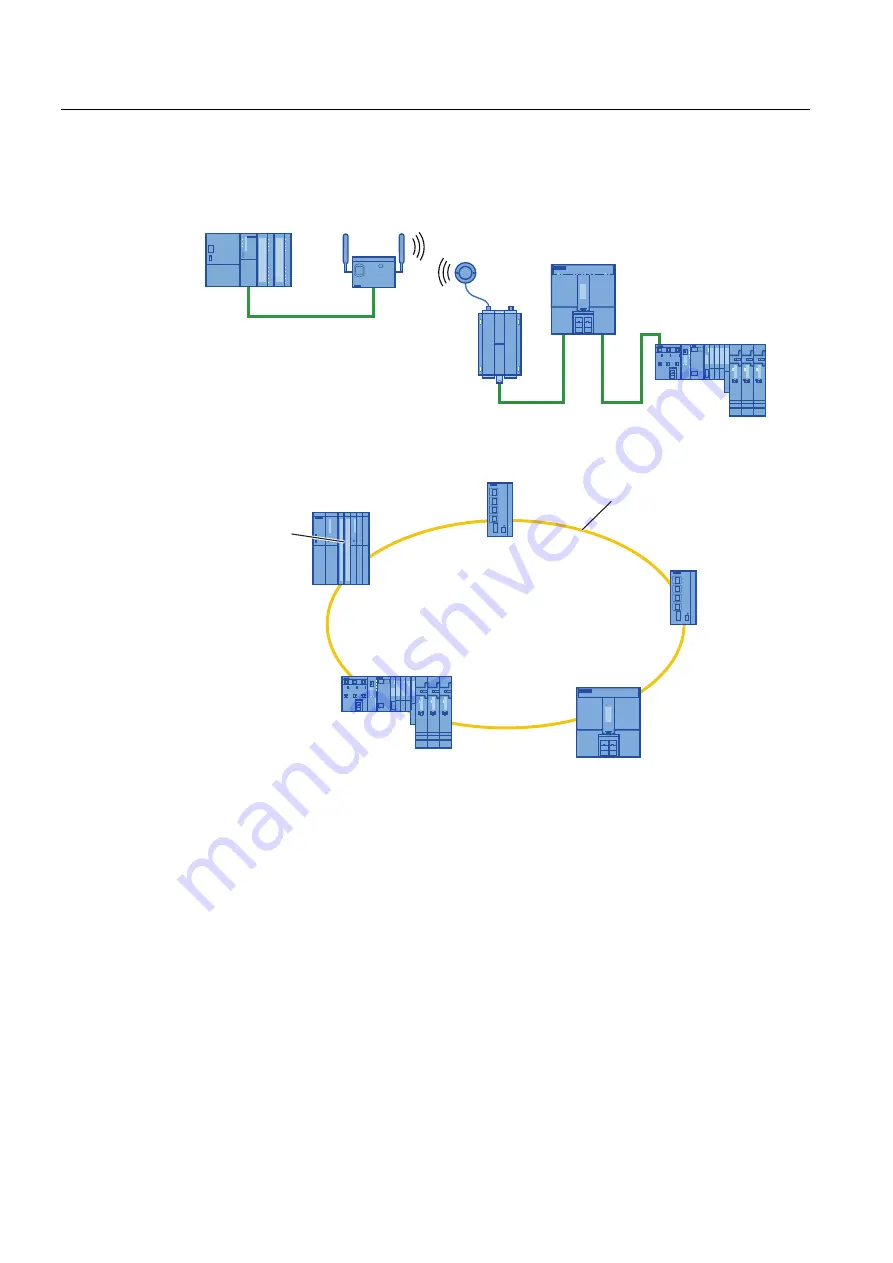
Figure 1-2
Cyclic data exchange between two I/O Controllers via IWLAN
,2FRQWUROOHU
6ZLWFK
6ZLWFK
,2FRQWUROOHU(76
ZLWK
,031'3&38
5HGXQGDQF\
PDQDJHU
5LQJZLWK053
3131&RXSOHU
6
Figure 1-3
Cyclic data exchange between two I/O Controllers via a redundant ring
Configuring
You either configure the PN/PN coupler using STEP 7 or a configuring tool which uses a
GSD file to integrate the PN/PN coupler.
You configure the I/O areas using virtual modules that are inserted from the hardware
catalog in HW Config onto slots of the PN/PN coupler, as real modules.
You select the I/O modules for the PN/PN coupler required for your application with STEP 7
in HW-Config in the hardware catalog. The output data of one side of the PN/PN coupler is
transferred as the input data of the other side and vice versa.
In dataset modules, dataset transfers take place between both PROFINET IO subnets. On
the X1 and X2 page, pairs of mutually fitting dataset module types must be configured on
equal slots, thus RD WRITE STO and RD READ STO or RD WRITE PUB and
RD READ PUB.
The input and output data are used to control the dataset transfer.


