background image

1-37

SIMATIC PC BI10/FI10/FI15, Technical Description
C79000-G7076-C773-03

1.4.15

Reset Button

The FI10, FI15 and BI10 devices are equipped with a reset button. When you
press the button, the device is cleared and reset. The PC is restarted.

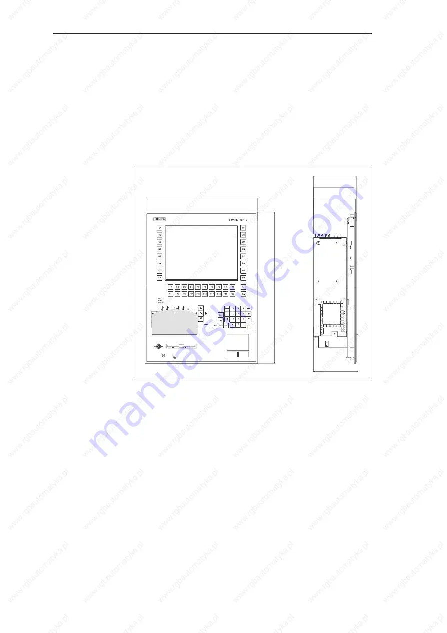
On the FI15, the reset button is integrated in the front panel under the cover
next to the floppy disk drive. The reset button can only be activated using a
pointed object (for example, the tip of a ballpoint pen or the end of an opened
paper clip). The following diagram of the FI15 shows the position of the reset
button.

125

121

335

450

127.5

132.5

Figure 1-33

   FI15 with Reset Button

System Unit

Summary of Contents for SIMATIC PC BI10

Page 1: ...48 71 325 15 05 www rgbautomatyka pl www rgbelektronika pl DATASHEET www rgbautomatyka pl www rgbelektronika pl OTHER SYMBOLS 6ES7646 1DC20 0HC0 6ES76461DC200HC0 6ES76461DC20 0HC0 6ES76461DC20 0HC0 6ES7646 1DC200HC0 6ES7646 1DC20 0HC0 6ES7646 1DC20 0HC0 6ES7646 1DC200HC0 6ES7646 1DC20 0HC0 6ES7646 1DC20 0HC0 SIEMENS ...

Page 2: ...ed with a wide variety of tools and having several testing stands at their disposal are a guarantee of the highest quality service OUR SERVICES ENCODERS SERVO DRIVERS LINEAR ENCODERS SERVO AMPLIFIERS CNC MACHINES MOTORS POWER SUPPLIERS OPERATOR PANELS CNC CONTROLS INDUSTRIAL COMPUTERS PLC SYSTEMS Repair this product with RGB ELEKTRONIKA ORDER A DIAGNOSIS Buy this product at RGB AUTOMATYKA BUY ...

Page 3: ...irect Key Module 4 Bus Board 5 Displays 6 Monitoring Module 7 Touch Screen 8 Hard Disk Drive 9 Floppy Disk Drive 10 Power Supply 11 Appendices Guidelines for Handling Electro statically Sensitive Devices ESD A Index PC BI10 FI10 FI15 Technical Description SIMATIC ...

Page 4: ...ices or components from other manufacturers which have been approved or recommended by Siemens This product can only function correctly and safely if it is transported stored set up and installedcorrectly and operated and maintained as recommended SIMATICR SIMATIC NETR and SIMATIC HMIR are registered trademarks of SIEMENS AG Third parties using for their own purposes any other names in this docume...

Page 5: ...ppy Disk Drive in the FI15 1 28 1 4 8 Removing and Installing the Hard Disk Drive 1 29 1 4 9 Removing and Installing an Expansion Module 1 31 1 4 10 Removing and Installing the Bus Board 1 32 1 4 11 Removing and Installing a Fan 1 33 1 4 12 Removing and Installing the Power Supply Unit 1 34 1 4 13 Removing and Installing the CPU Board 1 35 1 4 14 Connecting the MPI DP Interface 1 36 1 4 15 Reset B...

Page 6: ...emoving and Installing the Keyboard Controller 1 18 1 4 5 Replacing Backlight Tubes for Displays 1 20 1 4 6 Removing and Installing the Disk Drive for BI10 FI10 1 27 1 4 7 Removing and Installing the Disk Drive for FI15 1 28 1 4 8 Removing and Installing the Hard Disk Drive 1 29 1 4 9 Removing and Installing Expansion Modules 1 31 1 4 10 Removing and Installing the Bus Board 1 32 1 4 11 Removing a...

Page 7: ...IP20 Degree of protection SIMATIC PC BI10 Front IP20 Degree of protection SIMATIC PC FI15 Front IP65 when flap of diskette drive closed Safety Safetyclass Protection class I acc to VDE 0106 T1 1982 IEC 536 Safetyrequirements EN60950 acc to IEC 950 09 91 acc to DIN VDE 0805 A4 1997 Electromagnetic compatibility EMC Emittedinterference EN 55022 class B Noise immunity line fedinterference 2 kV to IEC...

Page 8: ...consumption per PCI slot 5V 2A 12V 0 3A 12V 0 05A 5V 2A 12V 0 5A 12V 0 1A A total of 8 A must not be exceeded at 5V Drives Floppy disk drive 3 5 1 44 Mbytes Hard disk drive 3 5 EIDE see Logbook LC Display SIMATIC PC FI15 FI15 VGA TFT FI15 SVGA TFT Display size display type 10 4 inches VGA TFT 10 4 inches SVGA TFT Resolution Colors 640 x 480 VGA 256K 800 x 600 SVGA 256K Contrast 100 1 60 1 Brightne...

Page 9: ...I DP interface isolated 9 pin sub D socket screw type locking Transmissionrate 9 6 Kbps to 1 5 Mbps assign parameters by software Operating mode isolated data lines A B control lines RTSAS RTS_PG 5V line voltage max 90 mA ground connection MPI DP connection cable shield Physicalinterface RS485 optically isolated PMCIAinterface PCMCIA 2 1 JEIDA 4 1 compatible Function display LEDs on FI10 FI15 Powe...

Page 10: ... deviation in their height can cause problems of contacting functional disorders or difficulties during their installation 290 106 7 7 6 2 54 30 PL 81 0 23 0 max A31 A1 All dimensions in mm 11 42 0 91 3 19 0 1 4 2 0 29 All dimensions in inches Figure 1 1 XT Module 290 114 3 7 6 2 54 30 PL 81 0 23 0 max A31 A1 All dimensions in mm 5 1 C18 C1 48 0 2 54 17 PL 11 42 4 5 0 91 3 19 0 1 0 2 1 89 0 1 0 29...

Page 11: ...1 6 SIMATIC PC BI10 FI10 FI15 TechnicalDescription C79000 G7076 C773 03 290 106 68 8 19 All dimensions in mm 11 42 4 2 0 32 All dimensions in inches Figure 1 3 Long PCI Module 5 V System Unit ...

Page 12: ... A VGA TFT display 1 0 45 A VGA TFT inverter 1 0 5 A SVGA TFT display 1 0 23 A SVGA TFT inverter 1 0 35 A STN display 1 0 23 A STN inverter 1 0 35 A Keyboardcontroller 0 12 A Touch Screen Controller 0 25 A 1 Either SVGA TFT VGA TFT or STN is installed 2 Optional The power supply permits a maximum current delivery of 70 W The following current values must not be exceeded Power Supply 5V 3 3V 12V 12...

Page 13: ... on the device is not affected Authorized SIEMENS maintenance and repair centers offer you a specialist maintenance service The user s guide supplies you with their addresses Caution The electronic components of the printed boards are extremely sensitive to electrostatic discharge When handling the boards precautionary measures must be taken Please refer to the guidelines for electrostatically sen...

Page 14: ...ools that you are using Wear a grounding wrist strap if you are handling components Leave components and modules in their packing until you are ready to install them Disconnect the PC from its power supply before plugging in or removing any modules or components Touch components and modules only on their edges Above all do not touch the connecting pins or printed conductors Do not operate the PC w...

Page 15: ...ly necessary if mounting screws are inaccessible in the installed state Remove the four screws see Figure 1 4 on the housing cover Then remove the housing cover When the housing cover is removed the following functional units can be seen in the housing Mother board Passive bus board Fan only in the FI15 Hard disk drive Floppy disk drive only with FI10 and BI10 Power supply Below SafeCard optional ...

Page 16: ...x to be moved out and tilted down by 90 in the installed state Please proceed as follows In the case of the FI10 remove all the screws that attach the computer box to the front plate In the case of the FI15 the computer box is also screwed to a shield plate Only remove the screws that attach the shield plate to the front plate The computer box of the FI15 can remain screwed to the shield plate Fig...

Page 17: ...n C79000 G7076 C773 03 Figure 1 6 Tilting the FI10 Box Down After removing the screws tilt the box together with the shield plate in the case of the FI15 backwards away from the front plate The box is held by a hinge below and a cord above System Unit ...

Page 18: ...1 13 SIMATIC PC BI10 FI10 FI15 TechnicalDescription C79000 G7076 C773 03 Figure 1 7 Removal for FI15 System Unit ...

Page 19: ...the FI15 Box Down When the front plate is tilted down the following components can be seen on the front plate LC display Inverter module LC display plug adapter Keyboard controller Touch screen controller optional Touch pad controller only with FI15 Touch pad adapter only with FI15 System Unit ...

Page 20: ... for touch screen controller opt LC display LCD plug adapter Keyboard controller Figure 1 9 Rear View of FI10 Front Plate LC display LCD plug adapter Keyboard controller Inverter Touch screen controller opt Touch pad adapter Touch pad Figure 1 10 Rear View of FI15 Front Plate System Unit ...

Page 21: ...and take the unit out The inverter module of the TFT SVGA display is fastened to the front plate with a special support plate the inverter module of the TFT VGA display is fastened to the front plate with two screws and the inverter module of the STN display is fastened to the front plate with four plastic rivets Release the screws or rivets The rivets are released by pushing their thorns out of t...

Page 22: ...1 17 SIMATIC PC BI10 FI10 FI15 TechnicalDescription C79000 G7076 C773 03 Figure 1 12 Removing the Display in the FI15 VGA TFT or SVGA TFT System Unit ...

Page 23: ...rane keyboard Caution Release the socket connector locking before removing the connecting cables to avoid any damage to the foil coating Before disconnecting all cables please write down their previous connections Release the four mounting screws then take out the keyboard controller module Please proceed in reverse order to reassemble the unit Figure 1 13 Removing the Keyboard Controller in the F...

Page 24: ...1 19 SIMATIC PC BI10 FI10 FI15 TechnicalDescription C79000 G7076 C773 03 Figure 1 14 Removing the Keyboard Controller in the FI15 System Unit ...

Page 25: ...light tube for the STN display is replaced as follows Remove the display from the front plate as described in Section 1 4 3 Place the display face down on a flat dust free surface Align the 17 metal lugs 3 at the left 7 on top 7 on bottom see Figure 1 15 Remove the 6 screws as shown in Figure 1 15 2 left 4 right Disassemble the rear panel of the display as shown in Figure 1 16 Lift the reflector f...

Page 26: ...5 TechnicalDescription C79000 G7076 C773 03 hooks hooks back plate screws screws screws hooks Figure 1 15 Removing the Screws and Metal Hooks back plate ÉÉÉÉÉÉÉÉÉÉÉÉÉÉ reflector film Change Figure 1 16 Removing the Tube System Unit ...

Page 27: ...on C79000 G7076 C773 03 ÉÉÉÉÉÉÉ ÉÉÉÉÉÉÉ cables cable positioning ÉÉÉÉÉÉ ÉÉÉÉÉÉ Figure 1 17 Position of the Tube Cables back plate ÉÉÉÉÉÉÉÉÉÉÉÉÉÉ As sheet reflector film ÉÉÉ ÉÉÉ reflector film o Ring at both ends X X Figure 1 18 Reassembly System Unit ...

Page 28: ...cessible from the side on the left as viewed from the rear Prise the white plastic tube socket out of the display housing using a medium sized slot screwdriver Holding the plastic not the cable pull the tube together with the socket carefully out of the display housing Install the new tube by following the above instructions in reverse order Ensure that the tube socket locks in the display housing...

Page 29: ...I15 TechnicalDescription C79000 G7076 C773 03 lamp unit B C t marking at the side of lamp unit s marking at the metal portion at the side of the module B C lamp unit back plate Figure 1 20 Sliding the Tubes In and Out System Unit ...

Page 30: ...1 22 2 left 2 right Disassemble the rear panel of the display as shown in Figure 1 23 Lift the reflector foil at the top edge of the display and remove the backlight tube carefully Insert the new backlight tube and cover it with the reflector foil The sealing rings O rings on the tube must be seated correctly and must be covered with reflector foil The cables connected to the tube must be laid in ...

Page 31: ...TechnicalDescription C79000 G7076 C773 03 back plate 4 screws 2 left 2 right Figure 1 22 Applying the Screwdriver ÉÉÉÉÉÉÉÉÉÉÉÉÉÉ ÉÉÉÉÉÉÉÉÉÉÉÉÉÉ Change reflector film Figure 1 23 Disassembling the Rear Panel of the Display System Unit ...

Page 32: ...nstructions in reverse order to install the new drive The new drive must be of the same type as the drive you removed Figure 1 24 Installing the Floppy Disk Drive in the FI10 Note The disk drive can be installed in the system housing rotated by 90 This is necessary with a mounting position in which the network connection is at the top The disk drive should not be operated with the disk slot at the...

Page 33: ...isk drive support backwards out of the front plate Release the two screws which fix the floppy disk drive to the support and remove the drive from the support Release the locking mechanism for the controller cable at the disk drive and pull the cable out of the connector Follow the above instructions in reverse order to install the new drive The new drive must be of the same type as the drive you ...

Page 34: ...s screwed to a support This support is fixed to the floor of the system housing with four screws Remove these screws and lift the support out of the unit Before disconnecting the cables please write down their previous connections Release the four screws which mount the floppy disk drive to the vibration reducing part of the support Take the hard disk drive out of the drive support Figure 1 26 Rem...

Page 35: ...1 30 SIMATIC PC BI10 FI10 FI15 TechnicalDescription C79000 G7076 C773 03 Figure 1 27 Removing the Hard Disk Drive from the Support Proceed in reverse order to install a new drive System Unit ...

Page 36: ...s in any way Proceed as follows Remove all connectors from the expansion module and write down where they belong Release the card retainers Release the screw on the slot plate of the module Pull the module carefully out of the slot Safecard optional Figure 1 28 Removing and Installing an Expansion Module DIP switches and jumpers of the new module should be set as those of the old module provided t...

Page 37: ...system unit as described in Section 1 4 1 Remove all modules from the slots proceed as described in Section 1 4 9 Release the screws on the exterior of the system housing and pull the bus board out of the mother board Figure 1 29 Removing and Installing the Bus Board Proceed in reverse order to install the bus board System Unit ...

Page 38: ...t as described in Sections 1 4 6 and 1 4 7 respectively The fan is fixed to the system housing with two plastic rivets Remove the rivets by pressing the thorns out of the body of the rivet from behind Disconnect the connector for the fan cable at the power supply and lift the fan out Figure 1 30 Removing and Installing the Fan Proceed in reverse order to install the fan Note You must install a fan...

Page 39: ...de of the computer housing and the screw on the port side see Figure 1 31 Lift the power supply unit slightly and disconnect the connecting cable from the mother board underneath the power supply unit To install the power supply proceed in reverse order The 90 W power supply unit for the SIMATIC PC BI10 FI10 FI15 is designed for AC input voltages of 120V 240V 6 10 and input currents of 1 4A 0 8A f...

Page 40: ...e power supply unit see Section 1 4 12 The module is still attached to the rear plate by three screws and to the port side of the computer housing with ten hexagonal bolts Remove these Then lift the module out of the computer housing Lift the side containing the PCMCIA slot out of the computer housing first 8 hexagonal bolts 2 hexagonal bolts Figure 1 32 Removing and Installing the CPU Module Proc...

Page 41: ... type locking 3 Switch on your IPC by removing the power supply plug Caution Risk of damage to the unit Before plugging in the connecting cables you must discharge the electro static charge of the cables and of your body by briefly touching a grounded object ESD guideline You can network up to 32 devices PC PG PLC or DP components via the MPI DP interface in one segment The interconnection to the ...

Page 42: ...et The PC is restarted On the FI15 the reset button is integrated in the front panel under the cover next to the floppy disk drive The reset button can only be activated using a pointed object for example the tip of a ballpoint pen or the end of an opened paper clip The following diagram of the FI15 shows the position of the reset button 125 121 335 450 127 5 132 5 Figure 1 33 FI15 with Reset Butt...

Page 43: ...set button is located on the box in the area of the slot plates This reset button can be activated by hand without the need for any additional tool The following figure shows the position of the reset button on the FI10 and BI10 devices Reset Button Figure 1 34 FI10 BI10 with Reset Button System Unit ...

Page 44: ...albeeps An error has occurred during the systemself test Check the hardware see also Chap 2 12 Every time a key is pressed a beep is heard and no characters appear Keyboard buffer overflow CTRL PAUSE Not ready message when trying to write to a diskette No diskette has been inserted Diskette has not been formatted Insertdiskette Formatdiskette Write protecterror when trying to write to a diskette D...

Page 45: ...1 40 SIMATIC PC BI10 FI10 FI15 TechnicalDescription C79000 G7076 C773 03 System Unit ...

Reviews: