background image

Description 


3.4 Accessories 


SCALANCE W786C 

18


Operating Instructions, 07/2019, A5E03692138-12 

Flexible connecting cable IWLAN QMA/N-Connect male/female 

Adapter cable for connecting a MIMO antenna with QMA connectors with the flexible 

connecting cables. Preassembled with two connectors QMA male and N-Connect female. 

pack of 3 


Length 

Article number 

1 m 

6XV1875-5JH10 

For railway applications, the following connecting cable is available Note: Scope of delivery: 

Pack of 1 


Length 

Article number 

1 m 

6XV1875-5VH10 

3.4.1.2


Antennas 


Note 
When you select an antenna, keep in mind the national approvals for your device. 
You can find additional information under Wireless approvals 

(

https://www.siemens.com/wireless-approvals

) 


The SCALANCE W786C-2IA RJ-45 uses internal omni antennas (3/4 dBi at 2.4 GHz or 5 

GHz).  


Type 

Properties 

Article number 

ANT792-4DN 

RCoax helical antenna, circular polarization, 

4 dBi, 2.4 GHz, N-Connect female. 

6GK5792-4DN00-0AA6 

ANT792-6MN 

Omni antenna, mast/wall mounting, 6 dBi 

2.4 GHz, N-Connect female 

6GK5792-6MN00-0AA6 

ANT792-8DN 

Directional antenna, mast/wall mounting, 14 

dBi 2.4 GHz, N-Connect female 

6GK5792-8DN00-0AA6 

ANT793-6DG 

Wide angle antenna, mast/wall mounting, 9 

dBi 5 GHz, 2 x N-Connect female 

6GK5793-6DG00-0AA0 

ANT793-6MN 

Omni antenna, mast/wall mounting, 5 dBi 5 

GHz, N-Connect female 

6GK5793-6MN00-0AA6 

ANT793-8DJ 

Directional antenna, mast/wall mounting, 18 

dBi 5 GHz, 2 x N-Connect female 

6GK5793-8DJ00-0AA0 

ANT793-8DK 

Directional antenna, mast/wall mounting, 23 

dBi 5 GHz, 2 x N-Connect female 

6GK5793-8DK00-0AA0 

ANT793-8DQ 

Circular polarized antenna, mast mounting, 

18 dBi, 5.8 GHz, 1 x N-Connector female 

6GK5793-8DQ00-0AA0 

ANT795-4MA 

Omni antenna, directly on the device, 3/5 

dBi 2.4 GHz and 5 GHz, IP30, R-SMA con-

nector male for direct installation on the 

device, angle connector adjustable 0° to 

180°. 

6GK5795-4MA00-0AA3 

Summary of Contents for SIMATIC NET SCALANCE W786C Series

Page 1: ... Industrial Wireless LAN SCALANCE W786C Operating Instructions 07 2019 A5E03692138 12 Introduction 1 Security recommendations 2 Description 3 Mounting 4 Connection 5 Technical data 6 Dimension drawing SCALANCE W786 7 Approvals 8 ...

Page 2: ...ly by personnel qualified for the specific task in accordance with the relevant documentation in particular its warning notices and safety instructions Qualified personnel are those who based on their training and experience are capable of identifying risks and avoiding potential hazards when working with these products systems Proper use of Siemens products Note the following WARNING Siemens prod...

Page 3: ...ng without an adapter wall mounting only 28 4 5 Installation with mounting plate 31 4 5 1 Fitting the mounting plate to a wall 31 4 5 2 Screwing the cover plate for the cable feedthrough to the mounting plate 33 4 5 3 Fitting the mounting plate to an S7 300 standard rail 34 4 5 4 Fitting the mounting plate to a DIN rail 35 4 5 5 Fitting the mounting plate to a mast 36 4 5 6 Fitting removing the SC...

Page 4: ... 07 2019 A5E03692138 12 5 9 Connecting external antennas 59 6 Technical data 61 6 1 Technical specifications SCALANCE W786C 2 61 6 2 Radiation patterns diagrams of SCALANCE W786 internal antennas 64 7 Dimension drawing SCALANCE W786 67 8 Approvals 69 Index 71 ...

Page 5: ...d These operating instructions apply to the following software version SCALANCE W786C with firmware as of version 8 31 Operating instructions Based on the operating instructions you will be able to install and connect up the SCALANCE W786 correctly Configuring the SCALANCE W786 and integration in a WLAN are not dealt with in this manual Documentation on the accompanying CD You will find introducto...

Page 6: ...iemens com industrialsecurity Siemens products and solutions undergo continuous development to make them more secure Siemens strongly recommends that product updates are applied as soon as they are available and that the latest product versions are used Use of product versions that are no longer supported and failure to apply the latest updates may increase customers exposure to cyber threats To s...

Page 7: ...G C PLUG KEY PLUG security PLUG contains sensitive data such as certificates keys etc that can be read out and modified Software security functions Keep the firmware up to date Check regularly for security updates of the product You will find information on this on the Internet pages Industrial Security https www siemens com industrialsecurity Inform yourself regularly about security advisories an...

Page 8: ...ction deals with the security keys and certificates you require to set up HTTPS HyperText Transfer Protocol Secured Socket Layer We strongly recommend that you create your own HTTPS certificates and make them available There are preset certificates and keys on the device The preset and automatically created HTTPS certificates are self signed We recommend that you use HTTPS certificates signed eith...

Page 9: ...f SNMPv1 is necessary SNMPv1 is classified as non secure Use the option of preventing write access The product provides you with suitable setting options If SNMP is enabled change the community names If no unrestricted access is necessary restrict access with SNMP Use SNMPv3 in conjunction with passwords HTTP HTTPS Telnet SSH Use secure protocols when access to the device is not prevented by physi...

Page 10: ...ng of the port is Closed Authentication Specifies whether or not the protocol is authenticated Encryption Specifies whether or not the transfer is encrypted Protocol Port number Port status Factory setting of the port Authentication SSH TCP 22 Open when configured Open Yes TELNET TCP 23 Open when configured Open Yes HTTP TCP 80 Open when configured Open Yes HTTPS TCP 443 Open when configured Open ...

Page 11: ...structions 07 2019 A5E03692138 12 11 Protocol Port number Port status Factory setting of the port Authentication DHCP UDP 67 68 Open when configured Closed No RADIUS UDP 1812 1813 Open when configured Closed No TFTP UDP 69 Open when configured Closed No ...

Page 12: ...Security recommendations SCALANCE W786C 12 Operating Instructions 07 2019 A5E03692138 12 ...

Page 13: ...r supply feed in adaptor Connector for Ethernet RJ 45 type LEDs Antenna connectors R1A1 R1A2 R1A3 Devices with one IWLAN interface 3 connectors Antenna connectors R2A1 R2A2 R2A3 Devices with two IWLAN interfaces 6 connectors Reset button Cable feedthrough Grounding connector thread M4 on the back of the device PLUG compartment not with W786C Figure 3 1 SCALANCE W786C ...

Page 14: ...of the type designations SCALANCE W786C 14 Operating Instructions 07 2019 A5E03692138 12 3 2 Structure of the type designations The type designation of a SCALANCE W786 is made up of several parts that have the following meaning ...

Page 15: ... on the version up to 8 plugs for sealing the housing Depending on the version up to 8 strain relief clamps 2 pin terminal block for the 24 VDC power supply SIMATIC NET Industrial Wireless LAN CD Note The mounting set with the holding plate does not ship with the device see Accessories Please check that the consignment you have received is complete If the consignment is incomplete contact your sup...

Page 16: ...l hose clips 6GK5798 8MG00 0AA0 Cables Industrial Ethernet Component Description Article number IE FC TP cable 4 x 2 Industrial Ethernet FastConnect TP standard cable GP 4 x 2 TP installation cable CAT6A for connection to IE FC RJ45 Plug 4 x 2 24 AWG Sold by the meter 6XV1878 2A Available in different lengths Lightning protection Component Description Article number LP798 1N Lighting protector wit...

Page 17: ... m 6XV1875 5CH20 5 m 6XV1875 5CH50 10 m 6XV1875 5CN10 For railway applications the following connecting cable are available Length Article number 1 m 6XV1875 5TH10 2 m 6XV1875 5TH20 5 m 6XV1875 5TH50 Flexible connecting cable N Connect N Connect Flexible connecting cable for connecting an antenna to a SCALANCE W device with N Connect connectors Preassembled with two N male connectors Length Articl...

Page 18: ...rticle number ANT792 4DN RCoax helical antenna circular polarization 4 dBi 2 4 GHz N Connect female 6GK5792 4DN00 0AA6 ANT792 6MN Omni antenna mast wall mounting 6 dBi 2 4 GHz N Connect female 6GK5792 6MN00 0AA6 ANT792 8DN Directional antenna mast wall mounting 14 dBi 2 4 GHz N Connect female 6GK5792 8DN00 0AA6 ANT793 6DG Wide angle antenna mast wall mounting 9 dBi 5 GHz 2 x N Connect female 6GK57...

Page 19: ... 6MT Omni antenna MIMO mounted on roof vehicle ceiling 5 7 dBi 2 4 GHz and 5 GHz 3 x QMA connector female 6GK5795 6MT00 0AA0 ANT793 8DL Directional antenna vertical horizontal polar ized 5 GHz 14dBi IP66 2xN Connect female 6GK5793 8DL00 0AA0 ANT793 8DP Directional antenna mast wall mounting 13 13 5 dBi 4 9 GHz and 5 GHz N Connect female 6GK5793 8DP00 0AA0 ANT795 4MX Omnidirectional antenna 2 2 5 d...

Page 20: ...10 m length Other flexible connecting cables are not permitted Notice for USA Canada Only one antenna per device can be used connected to R1A1 R1A2 or R2A1 R2A2 Note ANT793 8DK The antenna ANT793 8DK may only be used with the flexible connecting cable 6XV1875 5CN10 10 m length Other flexible connecting cables are not permitted Notice for USA Canada Only one antenna per device can be used connected...

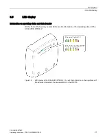
Page 21: ...formation on operating status and data transfer On the front of the housing several LEDs provide information on the operating status of the SCALANCE W786C 2 Figure 3 2 LED display of the SCALANCE W786C 2 You will find information on the significance of the individual elements in the documentation for the WLC700 ...

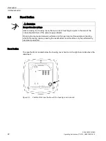
Page 22: ...he connecting terminals of the power supply adapter Opening the device and all work performed on the open device for example connecting and disconnecting cables pressing the reset button must therefore only be performed by electrical specialists Reset button The reset button is located below the housing cover beside on the right hand side above the cable feed Figure 3 3 Position of the reset butto...

Page 23: ...ury In this case install the device on an S7 300 standard rail or on a wall CAUTION Minimum distance to antennas Fit the device so that there is a minimum clearance of 20 cm between antennas and persons WARNING If a device is operated in an ambient temperature of more than 40 C the temperature of the device housing may be higher than 70 C The device must therefore be installed so that it is only a...

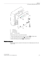
Page 24: ...ing plate You want to connect cables to the SCALANCE W786 for the power supply for Ethernet or for external antennas You want to use the reset button Removing the housing cover WARNING Danger from line voltage After removing the housing cover there is a risk of touching live parts in the area of the connecting terminals of the power supply adapter Opening the device and all work performed on the o...

Page 25: ...ly Follow the steps below to remove the housing cover 1 Remove the sealing caps from the housing cover position A in the figure above 2 Loosen the screws in the cover position B in the figure above 3 Remove the housing cover position C in the figure above Fitting the housing cover Fitting the housing cover is carried out in the reverse order Tightening torque for the cover screws 1 8 Nm ...

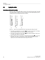
Page 26: ... Figure 4 2 Side view of a SCALANCE W786 with cables entering from different directions The cables are inserted from above position A in the previous schematic The housing of the SCALANCE W786 has an opening at the top for this purpose The cables are inserted from below position B in the previous schematic There is also an opening at the bottom for this purpose Cables inserted through a wall behin...

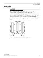
Page 27: ...ed The ground connector is located on the rear of the device M4 thread max screw length 20 mm Connect the grounding cable before you mount the device on a wall or on the optional mounting plate Once the device is mounted this connector is no longer accessible Place the supplied toothed washer directly on the rear of the device before screwing on the ground cable Only then can you be sure that ther...

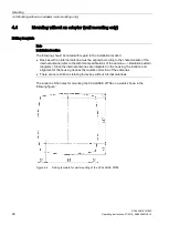
Page 28: ... aligned according to the characteristics of the internal antenna refer to the technical specifications of the antenna Radiation pattern diagrams Since the internal antennas are integrated in the housing the location and alignment of the housing decides the radiation direction of the antennas There are no restrictions relating to devices without internal antennas The location of the holes for moun...

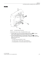
Page 29: ... of the SCALANCE W786 position A in the figure above Note the information in the section Connecting up cables 2 Secure the SCALANCE W786 to the wall with three screws position B in the figure above The screws are not supplied with the device The type and length of the screws depend on the type of wall Type of screw for wooden walls wood screw 4 x 30 mm for concrete walls 4 x 50 mm with 5 mm concre...

Page 30: ...in it is often not possible to use wall plugs for the screws To allow wall mounting even in this situation there are four M4 threaded holes on the rear of the SCALANCE W786 The drilling template is a square with sides 100 mm long The device can therefore be mounted on a wall with bolts through the wall Calculate the length of the required M4 screws as follows Screw length wall thickness 7 mm ...

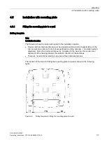
Page 31: ...ust be aligned according to the characteristics of the internal antenna refer to the technical specifications of the antenna Radiation pattern diagrams Since the internal antennas are integrated in the housing the location and alignment of the housing decides the radiation direction of the antennas There are no restrictions relating to devices without internal antennas The location of the holes fo...

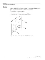
Page 32: ...l with four screws The screws are not supplied with the device The type and length of the screws depend on the type of wall Type of screw for wooden walls wood screw 4 x 30 mm for concrete walls 4 x 50 mm with 5 mm concrete plug for metal walls M4 x 25 mm with machine thread in the wall Figure 4 7 Fitting the mounting plate for the SCALANCE W786 to a wall ...

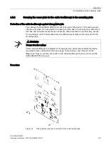
Page 33: ...ed on a wall this is the case and no further measures are necessary When mounted in any other way except for mounting on an S7 300 standard rail an additional cover plate must be screwed to the mounting plate WARNING Danger from line voltage If the cable feedthrough is subjected to strong water jets water can penetrate the device and create a live connection to the line voltage There is then a ris...

Page 34: ... with two M4 screws The screws are supplied with the assembly kit 4 5 3 Fitting the mounting plate to an S7 300 standard rail Procedure Figure 4 9 Side view of a mounting plate on an S7 300 standard rail Follow the steps below to fit the mounting plate to an S7 300 standard rail 1 Place the mounting plate with the two protruding catches on the top edge of the S7 300 standard rail position A in the...

Page 35: ... Mounting plate with fittings for DIN rail mounting Follow the steps below to fit the mounting plate to a DIN rail 1 Place the mounting plate with the two catches position A in the figure above on the upper edge of the DIN rail 2 Pull down the DIN rail sliding catch position B in the figure above and press the mounting plate against the DIN rail until the sliding catch engages ...

Page 36: ...e slots of the holding plate position A in the figure above 2 Place the hose clips at the required position round the mast 3 Place the free end of a hose clip through the quick release fastener You can swivel the clamping screw position B in the figure above to the side to adapt the diameter of the hose clip to the mast diameter The minimum mast diameter is 44 mm and the maximum mast diameter is 1...

Page 37: ...re 4 12 Fitting the SCALANCE W786 to a mounting plate Follow the steps below to fit a SCALANCE W786 to a mounting plate 1 Lead the cables into the housing of the SCALANCE W786 position A in the figure above Note the information in the section Connecting up cables 2 Fit the SCALANCE W786 so that the upper edge of the rear of the housing is below the two catches of the mounting plate position B in t...

Page 38: ...ition D in the figure above tightening torque 1 8 Nm Procedure for removing the device Follow the steps below to remove a SCALANCE W786 from a mounting plate 1 Loosen the screws between the SCALANCE W786 and mounting plate 2 Using a screwdriver or similar tool press down the two lugs on the lower edge of the mounting plate position C in the first figure in this section and release the SCALANCE W78...

Page 39: ... line voltage Once you have removed the housing cover there is the danger from line voltage in the area of the connecting terminals on the power supply adapter Opening the device and all work performed on the open device for example connecting and disconnecting cables pressing the reset button must therefore only be performed by electrical specialists ...

Page 40: ...u adhere to the VDE 0182 or IEC 62305 standard Suitable lightning protectors are available in the accessories of SIMATIC NET Industrial WLAN WARNING Danger due to lightning strikes Installing this lightning protector between an antenna and a SCALANCE W700 is not adequate protection against a lightning strike The LP798 1N lightening protector only works within the framework of a comprehensive light...

Page 41: ...wer supply units of the National Electrical Code table 11 b or SELV with LPS Limited Power Source EN 60950 1 If the power supply is designed redundantly two separate power supplies both power supplies must meet these requirements Exception Power supply with PELV according to VDE 0100 410 or IEC 60364 4 41 is also possible if the generated rated voltage does not exceed the voltage limits 25 VAC or ...

Page 42: ...ed before installation of the product for example by using an outlet box according to NEC or CEC When the device is located indoor The Ethernet Port RJ45 is considered a SELV circuit according IEC 60950 1 All connected Ethernet circuits must fulfill SELV requirements and shall be entirely contained within a single low voltage power distribution and within a single building Do not connect any exter...

Page 43: ...be installed in a manner to avoid tensile stress at the termination fittings in accordance with Article 501 10 B 1 4 of the NEC The PLTC cable for the power supply must be installed in accordance with Article 725 154 D 1 through D 4 of the NEC WARNING Cat Nos EAPN Wx yy zx Canadian installation only TC cable type and manufacturer shall be specified Listed QPOR Type JZ 604 TC manufactured by Heluka...

Page 44: ...ng Type PLTC or ITC Power supply adapter 100 to 240 VAC Round cable cross section with 6 to 8 mm diameter Three core cable with 0 5 1 5 mm2 cross sec tion of the individual cores Permitted tensile load at least 100 N Ethernet 1 IE FC TP standard cable GP 2 x 2 Type A article no 6XV1840 2AH10 2 IE TP Torsion Cable 2 x 2 Type C Article number 6XV1870 2F 3 IE FC TP Trailing Cable 2 x 2 Type C Article...

Page 45: ...table for high temperatures If temperatures in excess of 70 C occur on the cable or at the housing socket or the temperature at the branching points of the cables exceeds 80 C special measures need to be taken If the equipment is operated at an ambient temperature of 45 60 C only use cables with maximum permitted operating temperature of at least 90 C ...

Page 46: ... section Cables for the SCALANCE W786 Never wrap insulating tape adhesive tape or other materials around thinner cables to achieve the required diameter In this case neither the housing seal nor the strain relief clamps can fulfill their function Close all unused openings in the housing seal with the sealing plugs supplied with the SCALANCE W786 Do not use fillers or any other material under any c...

Page 47: ...You have the following options Connect cables preassembled with a connector Ethernet antennas by inserting the connector into the appropriate socket Secure antenna cables by tightening the sleeve nut of the connector key size SW8 You will find more information on this topic in the sections Connection for Industrial Ethernet and Connections for external antennas Note Connecting the grounding cable ...

Page 48: ...clamp must enclose the cable completely as shown by position B in the figure above 3 Press the strain relief clamp into the housing until the cable is located completely in the opening in the housing seal position C in the figure above 4 Seal all openings not required for cables with sealing plugs position D in the figure above 5 Fit these sealing plugs in a strain relief clamp The lower surroundi...

Page 49: ...Ethernet PoE With the SCALANCE W786 x RJ 45 power supply using Power over Ethernet PoE is also possible The devices support the standards 802 3at type 1 IEEE 802 3af and IEEE 802 3at type 2 With SCALANCE W786 2SFP Power over Ethernet is not possible in any situation Gigabit Ethernet When you connect to gigabit Ethernet the power supply is a phantom power supply over data wires 1 2 3 and 6 This cor...

Page 50: ... inserted in the left hand half of the housing When connecting the wires you should therefore make sure that the connector is oriented as shown in the following figure Figure 5 3 Position of the socket in the housing for the power supply Figure 5 4 Position of the connector when inserted in the socket of the housing Note Grounding connector The device has a grounding connector on the back of the d...

Page 51: ...2 51 Follow the steps below to connect a 24 VDC cable to a SCALANCE W786 1 Connect the supplied connector to the 24 VDC cable 2 Press the plug into the left hand half of the socket until it locks in place 3 Secure the power supply with a strain relief clamp as shown in the section Connecting the cables ...

Page 52: ...power supply adapter Input voltage options The optional power supply adapter is available in two versions Power supply adapter for 12 to 24 VDC direct voltage Power Supply PS791 2DC article number 6GK5791 2DC00 0AA0 Power supply adapter for 100 to 240 VAC alternating voltage Power Supply PS791 2AC article number 6GK5791 2AC00 0AA0 ...

Page 53: ...or with a DC power adapter no additional measures are necessary for use in a residential environment SCALANCE W786 with RJ 45 interface with AC power supply adapter PS791 2AC When using a SCALANCE W786 with a power supply adapter PS791 2AC 100 to 240 VAC the requirements for use in an industrial environment are met without any additional measures being necessary When used in a residential environm...

Page 54: ...p may damage the insulation under unfavorable circumstances You run the risk of encountering danger from line voltage through the strain relief clamp For a line with 100 to 240 VAC use an insulated strain relief clamp only this ships with the power supply adapter How to fit a power supply adapter The following figure shows how a power supply adapter is fitted A Securing screw B Pull out loop Figur...

Page 55: ...ment of the terminals is shown above 4 Secure the power supply cable with a strain relief clamp For more detailed information on this topic refer to the section Connecting the cables How to remove the power supply adapter NOTICE With careless disassembly the connector can break off Use only the dismantling loop position B if you take the power supply adapter out of the SCALANCE W786 This prevents ...

Page 56: ...the position of the Ethernet interface with the housing cover open Figure 5 6 Position of the Ethernet interface Device variant W786 x RJ 45 Follow the steps below to connect an Ethernet cable to a SCALANCE W786 with an RJ 45 jack 1 Insert the RJ 45 plug of the Ethernet cable in the jack of the SCALANCE W786 x RJ 45 2 Secure the Ethernet cable with a strain relief clamp Note Keep the dummy plugs K...

Page 57: ...2 1LH 1 x 1000 Mbps LC port optical single mode glass up to max 70 km 6GK5992 1AP00 8AA0 SFP992 1ELH 1 x 1000 Mbps LC port optical single mode glass up to max 120 km 6GK5992 1AQ00 8AA0 NOTICE The maximum operating temperature depends on the transceiver you are using The following temperature limits apply for the individual transceivers SFP992 1 60 C SFP992 1LD 55 C SFP992 1LH 50 C SFP992 1LH 50 C ...

Page 58: ...cument is on the CD that ships with the SCALANCE W786 or W786C NOTICE Insert and remove transceivers only when the power is off SFP SFP transceivers may only be inserted in or removed from an SFP slot when the power supply to the device has been turned off Position of the SFP slots The SFP slots are located below the housing cover to the left of the antenna sockets Figure 5 7 Position of the SFP s...

Page 59: ...st connect the cables to the R2 sockets if you are using more than one antenna for an interface After connecting the cables to the R1 sockets the R2 sockets are difficult to reach The following figure shows the interfaces of a SCALANCE W786 2 with the housing cover removed Figure 5 8 R1 Interface for the first wireless card R2 Interface for the second wireless card On devices with only one IWLAN i...

Page 60: ...e 2 Screw a terminating resistor to the unused socket if you use only one antenna on a port 3 Secure the antenna cable s with a strain relief clamp For more detailed information on this topic refer to the section Connecting the cables Note Terminating resistor Each WLAN interface has three antenna connectors Connectors that are not used must have a terminating resistor fitted see Accessories Page ...

Page 61: ...oInterface pdf Technical specifications Data transfer Ethernet transfer rate 10 100 1000 Mbps Wireless transmission rate 1 450 Mbps Wireless standards supported IEEE 802 11a IEEE 802 11b IEEE 802 11g IEEE 802 11h IEEE 802 11n Power supply standards supported Type IEEE 802 3at type 1 802 3af IEEE 802 3at type 2 Power over Ethernet Class Class 4 Attachment to Industrial Ethernet RJ 45 variants Quant...

Page 62: ...le Impedance 50 Ω nominal Internal antenna IA RJ 45 variants Quantity 2 Frequency range 2412 2480 MHz 4920 5875 MHz Electrical data Direct 24 VDC supply Supply voltage from terminal block socket 24 VDC Safety Extra Low Voltage SELV Permitted range 19 2 to 28 8 VDC Design Terminal block 4 terminals Properties Not electrically isolated Supply voltage from PoE Supply voltage from terminal block socke...

Page 63: ...uring transportation 40 C to 70 C Relative humidity During operation 95 at 25 C no condensation Operating altitude During operation 2 000 m above sea level at max 60 C ambient temperature Contaminant concentration According to IEC 60721 Degree of protection IP code IP65 Dimensions and weight Dimensions W x H x D 251 x 251 x 72 mm Weight Without power supply adapter 2 24 kg With power supply adapte...

Page 64: ...tion patterns diagrams of SCALANCE W786 internal antennas SCALANCE W786C 64 Operating Instructions 07 2019 A5E03692138 12 6 2 Radiation patterns diagrams of SCALANCE W786 internal antennas Horizontal radiation pattern 2500 MHz ...

Page 65: ... data 6 2 Radiation patterns diagrams of SCALANCE W786 internal antennas SCALANCE W786C Operating Instructions 07 2019 A5E03692138 12 65 Vertical radiation pattern 2500 MHz Horizontal radiation pattern 5800 MHz ...

Page 66: ...Technical data 6 2 Radiation patterns diagrams of SCALANCE W786 internal antennas SCALANCE W786C 66 Operating Instructions 07 2019 A5E03692138 12 Vertical radiation pattern 5800 MHz ...

Page 67: ...SCALANCE W786C Operating Instructions 07 2019 A5E03692138 12 67 Dimension drawing SCALANCE W786 7 Front view and view from above of the SCALANCE W786 ...

Page 68: ...Dimension drawing SCALANCE W786 SCALANCE W786C 68 Operating Instructions 07 2019 A5E03692138 12 ...

Page 69: ... at Siemens Industry Online Support https support industry siemens com cs ww en Using the search function at Industrial communication https support industry siemens com cs ww en ps 15859 cert Enter the entry ID of the relevant manual as the search item You will find the documentation for the SIMATIC NET products relevant here on the data storage medium that ships with some products Product CD prod...

Page 70: ...Approvals SCALANCE W786C 70 Operating Instructions 07 2019 A5E03692138 12 ...

Page 71: ...ension drawings 67 Documentation on the CD 5 E Ethernet 56 G Grounding 40 I Interfaces 61 L LED display 21 Lightning protection 40 Loading firmware 22 P Power supply 49 Protective caps 15 R Reset button 22 Resetting the device 22 Restart of the device 22 S Safety extra low voltage 40 41 Scope of delivery 15 SELV 40 T Technical specifications 61 61 Type designations 14 ...

Page 72: ...Index SCALANCE W786C 72 Operating Instructions 07 2019 A5E03692138 12 ...

Reviews: