background image

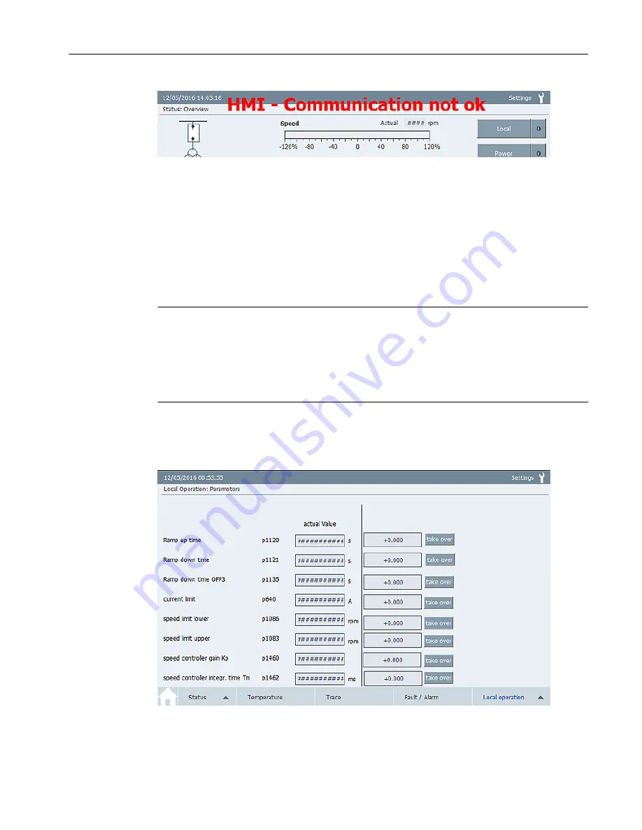
Figure 4-12 Example: Communication fault display

4.6.2

"Parameters" screen

You can change individual parameters with this screen. The screen is password-protected:
● User: gh
● Password: 150

Note
Qualified personnel
The "Parameters" screen must only be used for the specific Qualified personnel task.
Observe the documentation to be used, particularly regarding the warning and safety 

instructions. Qualified personnel are persons who, because of their training and experience, 

can recognize risks when handling these products/systems and avoid possible hazards.

Calling the screen
Press the <Local operation> button in the navigation bar. Select the "Parameters" screen. 

Figure 4-13 Example: "Parameters" screen

Screens

4.6 "Local Operation" screen selection

TP900 Function Manual

Function Manual, 10/2016, A5E39487277A

27

Summary of Contents for SIMATIC HMI TP900

Page 1: ...Function Manual Operator Panel 10 2016 Edition SIMATIC HMI TP900 www siemens com ...

Page 2: ......

Page 3: ...Medium voltage converters SIMATIC TP900 Function Manual Function Manual 10 2016 A5E39487277A Introduction 1 Safety notes 2 Description 3 Screens 4 Installing software 5 Service Support A ...

Page 4: ...e who based on their training and experience are capable of identifying risks and avoiding potential hazards when working with these products systems Proper use of Siemens products Note the following WARNING Siemens products may only be used for the applications described in the catalog and in the relevant technical documentation If products and components from other manufacturers are used these m...

Page 5: ...19 4 2 3 Power Cells screen 19 4 2 4 Drive screen 20 4 2 5 Infeed screen 21 4 3 Temperature screen selection 22 4 3 1 Temperature screen 22 4 4 Trace screen selection 23 4 4 1 Trace screen 23 4 5 Fault Alarm screen selection 25 4 5 1 Fault Alarm screen 25 4 6 Local Operation screen selection 26 4 6 1 Speed control screen 26 4 6 2 Parameters screen 27 4 6 3 Expert screen 28 5 Installing software 29...

Page 6: ...Table of contents TP900 Function Manual 6 Function Manual 10 2016 A5E39487277A ...

Page 7: ...ep these instructions for later use Read these instructions before you work with the operator panel and follow the instructions If you have suggestions for improving the document please contact our Service Center Additional documents Further information can be found in the following documentation Converter operating instructions Converter List Manual TP900 Function Manual Function Manual 10 2016 A...

Page 8: ...Introduction 1 1 About these instructions TP900 Function Manual 8 Function Manual 10 2016 A5E39487277A ...

Page 9: ...andling these products systems and avoid any possible dangers For your own personal safety and to prevent material damage when carrying out any work always observe the safety relevant instructions and the following five safety rules according to EN 50110 1 Working in a voltage free state Apply the five safety rules in the sequence stated before starting work Five safety rules 1 Disconnect the syst...

Page 10: ...Safety notes TP900 Function Manual 10 Function Manual 10 2016 A5E39487277A ...

Page 11: ... The operator panel communicates with the drive via Ethernet The operator panel has the following functions Touch screen operation Screen saver Language switching Local operation TRACE function Display of converter faults and alarms Fault memory can be read out via USB TP900 Function Manual Function Manual 10 2016 A5E39487277A 11 ...

Page 12: ...ne displays the current date and time Time and date are regularly synchronized with the converter The time of the Control Unit is overwritten with the time of the operator panel The bottom header line displays the name of the currently selected screen If you press the Settings button the menu for setting the screen appears You will find information in Section Setting the screen Description 3 2 Scr...

Page 13: ...tion A Single circuit converter B Double circuit converter Circuit breaker Transformer Drive comprising Basic Line Modules Motor Modules cooling unit Motor Figure 3 3 Configuration Main contents area This area displays the values and states of the converter The following sections contain a description of the display options Description 3 2 Screen display areas TP900 Function Manual Function Manual...

Page 14: ...ain the status changes to 0 The converter is Off and ready to switch on The Acknowledge all button resets the faults of all drive objects Alarms are hidden automatically You do not have to acknowledge the alarms A Help screen is stored on some screens The i button calls the Help screen Navigation bar You can call the individual functions in this area You can find the description in the following s...

Page 15: ...the converter The following functions are available Speed controlled Parameters Expert 3 3 Color information Additional information is displayed for some functions in the form of color fields The color fields have the following meanings Figure 3 4 Color information Description 3 3 Color information TP900 Function Manual Function Manual 10 2016 A5E39487277A 15 ...

Page 16: ...itions touch the touch screen within the displayed time Clean Screen You can clean the touch screen of the operator panel while it is switched on and a project is running After activation the touch screen is locked for operation within the configured interval The interval for the lockout can be between 5 and 30 seconds The time remaining until the end of the lockout is displayed on a progress bar ...

Page 17: ...ation bar 4 1 Overview screen The Overview screen displays the following information Actual values of the converter The current status of the converter Calling the screen Press the Home symbol in the navigation bar Figure 4 1 Overview screen TP900 Function Manual Function Manual 10 2016 A5E39487277A 17 ...

Page 18: ...e Calling the screen Press the Status button in the navigation bar Select the DC Link screen Figure 4 2 Example DC Link screen double circuit The following DC link limit values are specified The DC link voltage r3510 is shown as a bar The DC link overvoltage r6631 is shown in red The DC link undervoltage r6633 is shown in yellow Screens 4 2 Status screen selection TP900 Function Manual 18 Function...

Page 19: ...ecooling Unit screen double circuit The following standard limit values are shown in red They are fixed values on the screen not parameters Water temperature 10 C 46 C The value can be adapted to the specific project Differential pressure 3 bar 4 bar Conductivity 1 μS cm 1 2 μS cm 4 2 3 Power Cells screen The Power Cells screen displays the following information The cell status The cell ID The cel...

Page 20: ...uit 4 2 4 Drive screen The Drive screen displays the current status of the control bits The bit values are displayed as follows High signal green Low signal white This screen shows faults in the communication with the automation system The communication with the drive object e g vector is shown in the example Calling the screen Press the Status button in the navigation bar Select the Drive screen ...

Page 21: ... control bits The bit values are displayed as follows High signal green Low signal white This screen shows faults in the communication between the converter and the infeed Calling the screen Press the Status button in the navigation bar Select the Infeed 1 screen for a single circuit or the Infeed 2 screen for a double circuit Screens 4 2 Status screen selection TP900 Function Manual Function Manu...

Page 22: ...emperature screen displays the following information All temperatures measured in the converter control cabinet Fan status during operation Calling the screen Press the Temperature button in the navigation bar Screens 4 3 Temperature screen selection TP900 Function Manual 22 Function Manual 10 2016 A5E39487277A ...

Page 23: ...ter software The limit values are specified in the following parameters Alarm value p6514 p4102 if TM150 is used Fault value r6516 p4102 if TM150 is used The display does not contain any tolerances defined in the hysteresis parameter p6514 0 4 4 Trace screen selection 4 4 1 Trace screen The Trace screen offers the following options You can track up to eight values The scaling is adjusted automatic...

Page 24: ...lecting values Press the Setpoints button The overview for selecting the trace signals appears You can select up to eight signals that you want to record Figure 4 9 Example Selection of the trace signals Screens 4 4 Trace screen selection TP900 Function Manual 24 Function Manual 10 2016 A5E39487277A ...

Page 25: ... the Fault Alarm field A red square for an alarm A yellow square for a fault Calling the screen Press the Fault Alarm button in the navigation bar Fault display in the main contents area A Alarm F Fault Fault display in the navigation bar Figure 4 10 Example Fault Alarm screen You can find a description of the causes and the remedy for faults alarms in the converter List Manual Screens 4 5 Fault A...

Page 26: ... Step by step speed change with the arrow keys Figure 4 11 Example Speed Control screen Changing the speed 1 Switch the converter on with the Power button 2 Change the speed setpoint of the motor The following options are available Manual input via the keypad Step by step with the arrow keys The 0 button resets the speed setpoint to zero If the communication between the Control Unit and the operat...

Page 27: ...the documentation to be used particularly regarding the warning and safety instructions Qualified personnel are persons who because of their training and experience can recognize risks when handling these products systems and avoid possible hazards Calling the screen Press the Local operation button in the navigation bar Select the Parameters screen Figure 4 13 Example Parameters screen Screens 4 ...

Page 28: ...Take over button 4 6 3 Expert screen This screen is used for the configuration of the operator panel and for troubleshooting The Expert screen is intended for SIEMENS personnel only and is therefore password protected Screens 4 6 Local Operation screen selection TP900 Function Manual 28 Function Manual 10 2016 A5E39487277A ...

Page 29: ... follows 1 Copy the HMI software HMI_software_GH150_V zip from the product documentation CD of the converter to your PC 2 Unpack the file on the SD card The SIMATIC HMI folder is displayed on the SD card 3 Insert the SD card in the system slot of the operator panel System slot Data slot Figure 5 1 Card slots 4 Start the operator panel by switching on the power supply The software is installed 5 Co...

Page 30: ...Installing software 5 1 Setting up the operator panel TP900 Function Manual 30 Function Manual 10 2016 A5E39487277A ...

Page 31: ... If you wish to request on site service or order spare parts please contact your local office This office will contact the responsible service center on your behalf You can find your contact person in the relevant contact database www siemens com yourcontact www siemens com yourcontact Siemens Support for on the move You can obtain optimum support anywhere you go using the Siemens Industry Online ...

Page 32: ...Service Support TP900 Function Manual 32 Function Manual 10 2016 A5E39487277A ...

Page 33: ...s of the pumps 19 Current values of the cooling system 19 D DC link overvoltage 18 DC link undervoltage 18 Differential pressure 19 F Five safety rules 9 Function keys 14 H Header 12 L Language 16 Local service 31 M Main contents area 13 More information 31 N Navigation bar 14 O Operating system 16 R Runtime 16 S Screen 16 SD card 29 Spare parts 31 T Technical Support 31 Temperature limit values 2...

Page 34: ...Index TP900 Function Manual 34 Function Manual 10 2016 A5E39487277A ...

Page 35: ......

Page 36: ...Deutschland Siemens AG Industrie Sector Driver Technoligies and Industry Automation Postfach 48 48 90026 NÜRNBERG ...

Reviews: