background image

Betriebsanleitung 


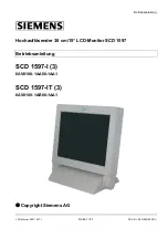
Hochauflösender 38 cm/15“ LCD-Monitor SCD 1597 


Betriebsanleitung 


SCD 1597-I (3) 

6AV8100-1AA00-1AA1 


SCD 1597-IT (3) 

6AV8100-1AB00-1AA1 


©

 Copyright Siemens AG 


LCD-Monitor SCD 1597-I


Seite 1 / 41 

DOC-Nr.: B30149DE3.DOC


Summary of Contents for SCD 1597-I

Page 1: ...leitung Hochauflösender 38 cm 15 LCD Monitor SCD 1597 Betriebsanleitung SCD 1597 I 3 6AV8100 1AA00 1AA1 SCD 1597 IT 3 6AV8100 1AB00 1AA1 Copyright Siemens AG LCD Monitor SCD 1597 I Seite 1 41 DOC Nr B30149DE3 DOC ...

Page 2: ...30149DE3 DOC Weitergabe sowie Vervielfältigung dieser Unterlagen Verwertung und Mitteilung ihres Inhaltes sind nicht gestattet soweit nicht ausdrücklich zugestanden Zuwiderhandlungen verpflichten zu Schadenersatz Alle Rechte vorbehalten 2006 All rights reserved ...

Page 3: ...en und Abgleichelemente 14 3 2 Abgleich des Konverters 14 3 2 1 Quick OSD Menü 15 3 2 2 OSD Menü 16 3 2 2 1 Struktur des On Screen Display Menü RGB 17 3 2 2 2 Struktur des On Screen Display Menü DVI 19 4 Technische Daten 20 4 1 Displaymodul 20 4 2 Stromversorgung 20 4 3 Betriebsbedingungen 20 4 4 Geräteschutz 20 4 5 Gehäuse 21 4 6 Eingangssignal 21 4 7 EU Konformitätserklärung über die EMV 21 1 Ov...

Page 4: ... 3 2 1 Quick OSD Menu 35 3 2 2 OSD Menu 36 3 2 2 1 OSD Menu Function RGB 37 3 2 2 2 OSD Menu Function DVI 39 4 Technical Data 40 4 1 Display Module 40 4 2 Power Supply 40 4 3 Operating Conditions 40 4 4 Protection 40 4 5 Enclosure 41 4 6 Input Signals 41 4 7 EU Declaration of Conformity on EMC 41 Abbildungen Abb 1 Abmessung des SCD 1597 I 10 Abb 2 Lage der Bedien und Abgleichelemente 14 ...

Page 5: ...rfreie Bilder Somit wird der SCD 1597 I auch höchsten ergonomischen Ansprüchen gerecht Kleine Bildauflösungen werden formatfüllend auf dem Monitor dargestellt Der SCD 1597 I kann bis zu 16 2 Mio Farben gleichzeitig darstellen Somit sind Darstellungen von Echtfarbbildern und Videos ohne Probleme möglich Der SCD 1597 I beinhaltet eine Konvertereinheit die es ermöglicht ihn mit einem Standard analoge...

Page 6: ...chreibung des SCD 1597 I Weiterhin wird auf Eigenschaften Einsatzbereich und Besonderheiten hingewiesen Kapitel 2 Inbetriebnahme Hier geht es im Wesentlichen um vorbereitende Arbeiten wie den Einbau die Aufstellung des Gerätes und seine Verkabelung Kapitel 3 Bedienung Dieses Kapitel beschreibt alle Bedien und Abgleichelemente des SCD 1597 I Kapitel 4 Technische Daten In diesem Kapitel werden alle ...

Page 7: ...age ist zur Einhaltung der elektromagnetischen Verträglichkeit nach dem EMV Gesetz angehalten Reparaturen Vor dem Öffnen des Gerätes ist die Versorgungsspannung abzuschalten Das Öffnen ist nur von autorisiertem Fachpersonal durchzuführen Erweiterungen oder Änderungen des Gerätes können das System beschädigen oder das EMV Verhalten beeinflussen Reinigung Vor der Reinigung ist das Gerät vom Netz zu ...

Page 8: ...handhaben sollten Sie folgende Hinweise befolgen Wenn elektronische Baugruppen gehandhabt werden ist für eine statische Entladung zu sorgen Dieses kann zum Beispiel durch das Berühren von geerdeten Gegenständen erreicht werden Gleiches gilt natürlich für zu benutzendes schutzisoliertes Werkzeug Dieses muss ebenfalls an einem geerdeten Gegenstand entladen werden Wenn Baugruppen aus dem System entfe...

Page 9: ...rsorgung Einbau in Ihr System unter Berücksichtigung technischer und ergonomischer Gesichtspunkte 2 1 Auspacken und Überprüfen der Einzelteile Nach Auspacken aller gelieferten Komponenten sind diese auf Vollständigkeit und Transportschäden Sichtkontrolle zu überprüfen Sollten hierbei Mängel festgestellt werden benachrichtigen Sie bitte die im Lieferschein ausgewiesene Serviceabteilung Sie sollten ...

Page 10: ...sbesondere im Bereich der Rückwand des Systems Bitte bedenken Sie dass eine überhöhte Temperatur zum Defekt bzw zur erheblichen Verkürzung der Lebensdauer des Monitors führen kann EMV Problematik Das vorliegende Gerät dient als Einbaukomponente in einer industriellen Anwendung Der Betreiber der Gesamtanlage ist zur Einhaltung der elektromagnetischen Verträglichkeit nach dem EMV Gesetz angehalten S...

Page 11: ...wendet Signalkabel von schlechter Qualität können starke Störungen und Schattenbildung im dargestellten Bild zur Folge haben 2 3 1 DVI Schnittstelle Die DVI Schnittstelle ist mit einem 29 poligen DVI Stecker realisiert Pin Signal 1 TMDS Data 2 2 TMDS Data 2 3 TMDS Data Shield 2 GND 4 5 6 DDC CLK 7 DDC DATA 8 Analog V Sync 9 TMDS Data 1 10 TMDS Data 1 11 TMDS Data Shield 1 GND 12 13 14 5 V Power In...

Page 12: ...Frei 5 Frei 6 GND ROT 7 GND GRÜN 8 GND BLAU 9 Frei 10 GND 11 Frei 12 Frei 13 H Sync 14 V Sync 15 Frei 15 14 13 12 11 10 9 8 7 6 5 4 3 2 1 2 3 3 Touch Schnittstelle RS232 Der Touch kann über die USB bzw RS232 Schnittstelle angeschlossen werden Pin Signal 1 DCD 2 RxD 3 TXD 4 DTR 5 GND 6 DSR 7 RTS 8 CTS 9 RI Wichtig Signaldefinition vom Host z B PC LCD Monitor SCD 1597 I Seite 12 41 DOC Nr B30149DE3 ...

Page 13: ... Netzteil wird direkt in die 12 VDC Versorgungsspannungsbuchse gesteckt 2 4 Elektrische Inbetriebnahme Bevor Sie den SCD 1597 I an die Stromversorgung anschließen sollte überprüft werden ob der Stecker für das Eingangssignal korrekt angesteckt und verschraubt ist Zeigt der Monitor nach Einschalten kein Bild kann dies mehrere Ursachen haben wie kein Eingangssignal angeschlossen ein Synchronisations...

Page 14: ...e Normung bezüglich des Videoausgangssignals von Grafikkarten gibt erfolgt beim erstmaligen Einschalten automatisch eine Anpassung an die jeweilige Grafikkarte OSD Menü Quick OSD Menü Das On Screen Display OSD ist ein Menüsystem dass auf den Bildschirm dargestellt wird Mit Hilfe des Menüsystems und den beschriebenen Bedienelemente sind alle Einstellungen des Monitors durchzuführen Zur Steuerung de...

Page 15: ...en Aufruf durch die Taste SET Funktion Einstellen Einstellwert Beschreibung Einstellbereich 0 bis 100 über Einstelltasten Helligkeit einstellen Einstellbereich 0 bis 100 über Einstelltasten Kontrast einstellen Aufruf durch die Taste Funktion Einstellen Einstellwert Beschreibung Quellenauswahl digital DVI analog RGB Auswahl durch erneutes Drücken der Taste Selektion der Eingangsquelle Abgleich durc...

Page 16: ...ahl nach links MENÜ OSD Aufruf Hauptmenü Untermenü auswählen SET Punkt im Hauptmenü Untermenü von oben nach unten durchgehen auswählen Aufruf durch die Taste Men Das OSD variiert abhängig von der gerade dargestellten Signalquelle Die nachfolgenden Unterkapitel beschreiben die OSD Funktionalität bei dargestellten RGB VGA und DVI Signal LCD Monitor SCD 1597 I Seite 16 41 DOC Nr B30149DE3 DOC ...

Page 17: ...Drei festdefinierte und eine frei einstellbare Farbtemperatur stehen zur Auswahl Wird VAR aktiviert erscheinen für R G und B jeweils ein Einstellbalken Einstellbereich 0 bis 100 50 entspricht Faktor 1 Optionen 1 OSD Auswahl zwischen neun festdefinierten OSD Positionen Position OSD auswählen OSD H Position Einstellbereich 0 bis 100 über Einstelltasten OSD Menü in horizontaler Richtung verschieben O...

Page 18: ...dert einen erneuten Bildabgleich während der Darstellung eines Videosignals bei kurzzeitigen Störungen auf den Synchronisationssignalen RGB Signal 1 verriegeln EIN Taste Standardeinstellung AUS Bei EIN Das gerade dargestellte Videotiming wird gespeichert und mit einer höheren Toleranz in H und V Frequenz verarbeitet D h die Einstellungen dieses Timings werden immer ver wendet selbst wenn durch Stö...

Page 19: ...leich Mode3 verwenden der eingestellten Parameter mit komplett automatischem Abgleich ohne den automatischen Frequenz Abgleich H sichtbar 100 bis 2000 über Einstelltasten Horizontale Bildauflösung einstellen wichtigster Parameter V sichtbar 100 bis 2000 über Einstelltasten Vertikale Bildauflösung einstellen wichtigster Parameter H total 100 bis 2500 über Einstelltasten Anzahl der gesamten Pixel in...

Page 20: ...T Cold Cathode Fluorescent Tube Helligkeit typisch ca 370 cd m 4 2 Stromversorgung Eingangsspannung 11 4 12 6 VDC Leistungsaufnahme Normalbetrieb 18 W Leistungsaufnahme StandBy ca 5 W Eingangsspannung ext Netzteil 100 240 VDC Leistungsaufnahme Normalbetrieb 25 W Leistungsaufnahme StandBy ca 5 W 4 3 Betriebsbedingungen Betriebstemperatur 0 bis 40 C Lagertemperatur 20 bis 60 C Relative Luftfeuchte B...

Page 21: ... an 75 Ω Bandbreite 300 MHz 3dB Impedanz 75 Ω Synchronisation Sep Sync TTL Sync on green Composite Sync H Frequenz 30 bis 97 KHz V Frequenz 50 bis 72 Hz 4 7 EU Konformitätserklärung über die EMV Produkt LCD Monitor SCD 1597 I Prüfgrundlagen EG Rahmenrichtlinien Nr 89 336 EWG Nr 73 23 EWG Angewande harmonisierte Normen EN 61000 6 4 EN55022 Class A Störemission EN 61000 6 2 Störfestigkeit EN 60950 S...

Page 22: ...ions High Resolution 38 cm 15 LCD Monitor SCD 1597 I IT Operating Instructions SCD 1597 I 3 6AV8100 1AA00 1AA1 SCD 1597 IT 3 6AV8100 1AB00 1AA1 Copyright Siemens AG LCD Monitor SCD 1597 I Page 22 41 DOC No B30149DE3 DOC ...

Page 23: ... LCD Monitor SCD 1597 I Page 23 41 DOC No B30149DE3 DOC No part of this document may be reproduced or transmitted without express permission Violations will result in prosecution All rights reserved 2006 All rights reserved ...

Page 24: ... 29 2 2 Installing the LCD Monitor 30 2 3 Cable Connections and Pin Assignments 31 2 3 1 DVI Interface 31 2 3 2 VGA Interface 32 2 3 3 Touch Interface 32 2 3 4 Power Supply 33 2 4 Electrical Installation 33 3 Operation and Alignment 34 4 Technical Data 40 4 1 Display Module 40 4 2 Power Supply 40 4 3 Operating Conditions 40 4 4 Protection 40 4 5 Enclosure 41 4 6 Input Signals 41 4 7 EU Declaration...

Page 25: ...te of 50 Hz the screen remains flicker free The SCD 1597 I thus fulfils even the strictest ergonomic requirements Pictures of lower resolution are expanded to fill the screen The SCD 1597 I can display up to 16 2 Mio colors This allows to show true color images and videos The LCD monitor contains special hardware to convert a standard analogue VGA and digital DVI video signal Compatibility with co...

Page 26: ...ion of the SCD 1597 I including its properties application areas and special features Chapter 2 Installation This chapter is mainly concerned with preparing the LCD monitor for use its installation and cabling Chapter 3 Operation All operations and adjustment possibilities for the SCD 1597 I are described here Chapter 4 Technical Data This chapter contains technical details such as dimensions powe...

Page 27: ...r building into industrial systems The operator of the entire plant is responsible for maintaining electromagnetic compatibility according to EMC law Repairs Before the unit is opened the supply voltage must be switched off Only authorized persons may open the unit Additions or changes to the unit may damage the system or affect its EMC behavior Cleaning The unit must be isolated from the power su...

Page 28: ... service technician are handling such assemblies then the following precautions should be observed When such assemblies are being handled a means of electrostatic discharge must be available This can be for example a grounded object which can be touched to discharge electrostatic voltages This applies to all insulated used tools They must also be discharged at grounded object When assemblies are r...

Page 29: ...nd power supply Building into your system bearing in mind technical and ergonomic aspects 2 1 Removing the Packaging and Checking Individual Parts After unpacking all the delivered components they should be checked for completeness and for possible transport damage visual inspection If any deficiencies are found then please contact the service department given on the delivery note Have the deliver...

Page 30: ...t that the rear of the system is kept free Please bear in mind that increased temperatures can lead to defects and to a significant reduction in the lifetime of the monitor EMC Problems This LCD monitor is a piece of equipment designed for building into an industrial system The operator of the entire plant is responsible for maintaining electromagnetic compatibility according to EMC laws Safety Pr...

Page 31: ...r the VGA signals Low quality cables can result in interference and shadowing on the display 2 3 1 DVI Interface The DVI interface is a 29 pin DVI connector Pin Signal 1 TMDS Data 2 2 TMDS Data 2 3 TMDS Data Shield 2 GND 4 5 6 DDC CLK 7 DDC DATA 8 Analogue V Sync 9 TMDS Data 1 10 TMDS Data 1 11 TMDS Data Shield 1 GND 12 13 14 5 V Power In 15 GND 16 Hot Plug Detect 17 TMDS Data 0 18 TMDS Data 0 19 ...

Page 32: ... Not used 6 GND RED 7 GND GREEN 8 GND BLUE 9 Not used 10 GND 11 Not used 12 Not used 13 H Sync 14 V Sync 15 Not used 15 14 13 12 11 10 9 8 7 6 5 4 3 2 1 2 3 3 Touch Interface The Touch will be connected via the RS232 interface Pin Signal 1 DCD 2 RXD 3 TXD 4 DTR 5 GND 6 DSR 7 RTS 8 CTS 9 RI Important Signal defined by the Host e g PC LCD Monitor SCD 1597 I Page 32 41 DOC No B30149DE3 DOC ...

Page 33: ...ctly into the 12 VDC socket 2 4 Electrical Installation Before connecting the SCD 1597 I to the power supply check whether the input signal connector is plugged in properly and that the screws are tightened There are many possible reasons why an image might fail to appear on the display after it has been switched on no input signal connected no synchronization signal connected horizontal and verti...

Page 34: ...ions of the keys are described in chapter 3 2 1 and 3 2 2 3 2 Adjusting the Converter The first time the unit is switched on it will automatically adjust to the graphic card currently being used OSD Menu Quick OSD Menu The On Screen Display OSD is a menu system which is shown on the display With the help of OSD and the described control elements all adjustments of the monitor are executable There ...

Page 35: ...e in picture characteristics Following adjustments can be done via the Quick OSD menu Invoke via key SET Function Adjustment value Description Range 0 to 100 via key Contrast adjustment Range 0 to 100 via key Brightness adjustment Invoke via key Function Adjustment value Description Source select Digital DVI analog RGB Press key to select Selection of input source Press key to start the adjustment...

Page 36: ...the left Power on switch MEN Start OSD Select the main menu submenu SET Scroll down or select menu idem in main menu submenu Invoke via key Enter The appearance of OSD depends on selected signal source OSD functionality by showing RGB VGA and digital input DVI signals are described in the following captures LCD Monitor SCD 1597 I Page 36 41 DOC No B30149DE3 DOC ...

Page 37: ...9300 VAR color temperature adjust color three defined and one adjustable color temperatures are for selection Activate VAR for RGB shows up an adjustment beam 0 to 100 50 correspond to factor 1 Option 1 OSD select between nine defined OSD positions f define position OSD OSD H Position setting range 0 to 100 through key move OSD menu in horizontal position OSD V Position setting range 0 to 100 thro...

Page 38: ... signals Inhibits new auto alignment during display of a video signal when short term noise is present on synchronous signals Lock RGB Signal 1 ON Key Standard setting OFF At ON The video timing currently shown will be stored and processed with higher tolerance in H and V frequency I e the settings of this timing will always be used even if variations in H and V frequency will occur by noise Preve...

Page 39: ...ing parameter and perform an auto adjustment without an automatic frequency adjustment H resolution 100 to 2000 through key Horizontal image resolution important parameter V resolution 100 to 2000 through key Vertical image resolution important parameter H total 100 to 2500 through key Whole pixel per line important parameter H Start 0 to 750 through key Number of Pixels from H sync start to image...

Page 40: ...uorescent Tube Brightness typical approx 370 cd m 4 2 Power Supply Input voltage 11 4 12 6 VDC Power consumption normal operation 18 W Power consumption Standby approx 5 W Input voltage ext Power Supply 100 240 VDC Power consumption normal operation 25 W Power consumption Standby approx 5 W 4 3 Operating Conditions Operating temperature 0 to 40 C Storage temperature 20 to 60 C Relative humidity in...

Page 41: ...at 75 Ω Bandwidth 300 MHz 3dB Impedance 75 Ω Synchronization Sep Sync TTL Sync on green Composite Sync H Frequency 30 to 97 kHz V Frequency 50 to 72 Hz 4 7 EU Declaration of Conformity on EMC Product LCD Monitor SCD 1597 I Test foundations EU framework guidelines No 89 336 EWG No 73 23 EWG Harmonized standards used EN 61000 6 4 EN 55022 Class A Interference emissions EN 61000 6 2 Interference resi...

Reviews: