Industrial Ethernet Switches
3
Network topology and network configuration
The SCALANCE XB-000/XB-000G switches are typically in-
stalled with the stations to be connected in a control cabinet
or control box. When configuring the network, it is necessary
to observe the following boundary conditions:
• Length of the TP cable between two SCALANCE XB-000/
XB-000G switches
- max. 100 m
- max. 10 m via patch cable with TP Cord
- max. 100 m via Industrial Ethernet FC Outlet RJ45,
IE FC Standard Cable and TP Cord
• Length of fiber-optic cables:
- max. 3 km with Industrial Ethernet FO cables
multimode
- max. 26 km with Industrial Ethernet FO cables
singlemode
Diagnostics
The following information is indicated on the device by means
of LEDs:
• Power
• Port status
• Data traffic
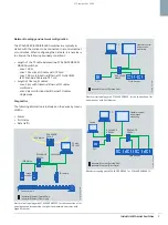
Electrical star topology with SCALANCE XB005G for the connection of ter-
minal devices and connection to higher-level network structures with
Gigabit Ethernet
Electrical star topology with SCALANCE XB005 for the connection of ter-
minal devices with Fast Ethernet
Mixed star topology with SCALANCE XB004-1 or SCALANCE XB004-1G
PC with
CP 1623
IP camera
Image
scanner
Conveyor belt
G_IK10_XX_10259
SCALANCE
XB005G
SCALANCE
X308-2
1000 Mbit/s
1000 Mbit/s
1000 Mbit/s
Industrial Ethernet (Twisted Pair)
Industrial Ethernet (Fiber Optic)
PC
Field devices
PLC
Operator control
and process
monitoring
*B,.B;;B
Industrial Ethernet (Twisted Pair)
SCALANCE
XB005
Laptop
PC
PLC
Operator control
and process
monitoring
Field devices
*B,.B;;B
Industrial Ethernet (Twisted Pair)
Industrial Ethernet (Fiber Optic)
SCALANCE
XB004-1
SCALANCE
XB004-1
BS_SCALANCE_XB000_0409_en.fm Seite 3 Dienstag, 21. April 2009 1:56 13
© Siemens AG 2009


