2
Housing and cover:
Permanent mold alloy 356 aluminum castings.
Precision CNC machining of all gear, shaft and motor surfaces.
Gear Train:
240 to 1 Reduction.
Bearings:
Maintenance free sealed – both main and gear shaft.
Motor:
12 VDC, 4 pole compound series/permanent magnet.
Brake:
Hold up, hold down =165ma @ 12VDC
Operating Voltage:
11 – 16 VDC.
Operating Current:
Up = 6 – 15 A @ 12 VDC, Down = 6 – 15 A @ 12 VDC.
Circuit Breaker
7 Amp Auto-reset.
S
TANDARD
F
EATURES
Makeup of the S-40EXIT Gate Mechanism – Internal:
•
Relay panel assembly complete with down rate resistors and over-speed control.
•
Auto-reset circuit breaker motor protection.
•
Standard Gate Control Relays.
•
Adjustable snap action contact actuating cam for power up and power down (posi-
tions 7 & 8).
•
Adjustable contact and cam for flashing light control (position 9).
•
Adjustable contact and cam for bell control (position 10).
•
Adjustable horizontal snub contact and cam (position 11).
Note: Contact cams are factory set as shown on wiring diagram, page 3.
•
Adjustable snub resistors to set up time and down time (.80 ohm max).
•
115 VAC Defroster located under motor end and wired to terminal block position 1
with insulated nuts.
•
Mechanism serial number located on motor housing label.
•
Maintenance switch assembly with stop bracket – see page 13.
Makeup of the S-40EXIT Gate Mechanism – External:
•
Lifting eyebolt.
•
Shaft ends with 1”-8 UNC nuts, lock washers and hub keys.
•
Mounting bolts and saddles for 5” pipe mounting.
•
Mechanism support clamp for 5” pipe mounting.
•
2” x 42” long liquid tight conduit with one straight and one 45 degree connector.
•
Mechanism serial number stamped on top outside of cabinet.
O
PTIONS
•
Additional contact and cam.
•
Special contact cam settings.
•
Special defroster - 230 VAC, 12 or 24 VDC.
S
PECIFICATIONS
Summary of Contents for S-40EXIT
Page 5: ...3 ...
Page 20: ...18 S 40EXIT Gate Exploded View ...
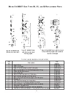
Page 21: ...19 S 40EXIT Gate Replacement Parts ...
Page 27: ......


