


RUGGEDCOM WIN5151
Installation Guide
Chapter 2
Installing the Subscriber Unit
Unpacking the Subscriber Unit
9
2. Unpack and inspect the subscriber unit components. For more information, refer to
.
3. Mount the subscriber unit to a pole, wall or tower. For more information, refer to
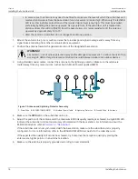
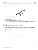
4. Install and connect the antenna(s). For more information, refer to
Section 2.6, “Installing the Antennas”
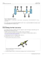
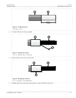
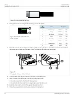
5. Assemble the PoE cable. For more information, refer to
Section 2.8.4, “Assembling the PoE Connector”
6. Make sure the subscriber unit is grounded. For more information, refer to
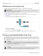
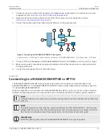
7. Connect the subscriber unit to a power source and the network. For more information, refer to
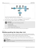
8. Seal all cable connections. For more information, refer to
Section 2.9, “Weatherproofing the Subscriber Unit”
.
9. Configure the subscriber unit. For more information, refer to
Section 3.1, “Configuring the Subscriber Unit”
.
Section 2.2
Unpacking the Subscriber Unit
The following items are included in the RUGGEDCOM WIN5151 package:
Item
Quantity
RUGGEDCOM WIN5151 Subscriber Unit
1
RUGGEDCOM WIN1010 AC Power Injector
1
Radio Frequency (RF) antenna cables, 5 m (16.4 ft) long
2
Pole/wall/tower mounting kit
1
RJ45 PoE Connector Kit
1
When unpacking the subscriber unit, do the following:
1. Inspect the package for damage before opening it.
2. Visually inspect each item in the package for any physical damage.
3. Verify all items are included.
If any item is missing or damaged, contact Siemens for assistance.
Section 2.3
Site Preparation and Precautions
Before installing the subscriber unit and or antenna(s), it is important to plan the the complete installation and
make sure the appropriate safe guards are in place.
Site Selection
Consider the following recommendations when selecting an appropriate site for the subscriber unit and
antenna(s):