5
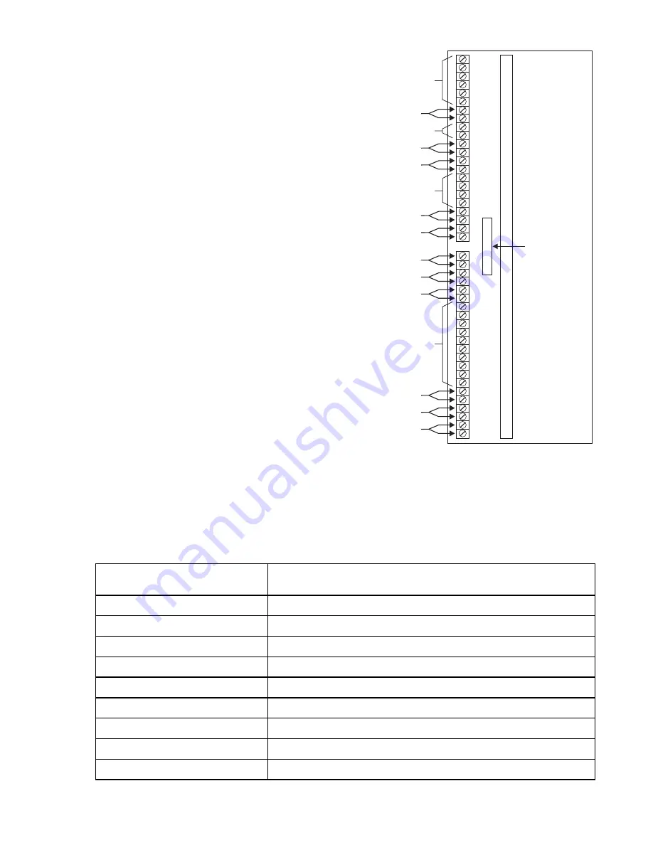
Figure 3
Description of the RCM-1 Terminals
The RCM-1 can be connected in many different ways. Table 2 describes the various applications. The
block diagrams below show the possible configurations.
Note:
Polarity must be observed
with all riser connections.
Odd pins are
hi
side while
even pins are
lo
side. See
the separate wiring
connections for the ACM/
TBM and the OCC shown
in Figure 12.
TABLE 2
RCM-1 APPLICATIONS
Application No.
(See Corresponding Diagram)
Configuration
1
Typical Style 4 installation
2
Style 4 installation with a Style 4 output only extension
3
Typical Style 7 installation
4
Style 7 installation with a Style 4 extension
5
Style 4 installation with fiber optic transmission
6
Style 4 fiber optic with a Style 4 fiber optic output only extension
7
Style 7 fiber connections with a Style 4 output only fiber extension
8
Combination wire and fiber installation
9
Style 4 Repeater Installation
1
2
3
4
5
6
7
8
9
10
11
12
13
14
15
16
17
18
19
20
21
22
1
2
3
4
5
6
7
8
9
10
11
12
13
14
15
16
17
18
19
20
21
22
PORT C: Copper Interface, Transmit, Style 4 (CT4)
PORT B: Copper Interface, Receive, Style 4 (BR4)
PORT B: Copper Interface, Transmit, Style 4 (BT4)
PORT B: Copper Interface, Receive, Style 7 (BR7)
PORT B: Copper Interface, Transmit, Style 7 (BT7)
NOT USED
NOT USED
NOT USED
NOT USED
PORT B: Fiber Interface, Style 4 (BF4)
PORT B: Fiber Interface, Style 7 (BF7)
PORT C: Fiber Interface, Style 4 (CF4)
CABLE TO
MMB OR PSR
P/N 555-190967
PORT D: Copper Connection To The OCC
PORT D: Copper Connection To The OCC
PORT A: Copper Connection To The ACM
RCM-1
OMM-1
or
OMM-2


