Technical Instructions
RCC10U Room Temperature Controller
Document Number 155-712
for Two-pipe Fan Coil Units
September 27, 2007
Page 6
Siemens Industry, Inc.
Table 2. DIP Switches.
DIP Switch No.
Description
Position ON
Position OFF
1
Fan control
Fan control is temperature-
dependent in all operating modes
Fan control in Normal
operation is temperature-
independent
1
2
Operating mode changeover
via an external switch
Changeover between Normal
operation and Energy Saving
mode
Changeover between Normal
operation and Standby
1
3
Operating action of switch for
external operating mode
changeover
Changeover activated when
contact of switch is closed (NO)
1
Changeover activated when
contact of switch is open (NC)
4
Standby
Freeze Protection function
disabled
Freeze Protection function
enabled
5
Switching differential
2°F (1°C) in Heating mode
1
1°F (0.5°C) in Cooling mode
1
7°F (4°C) in Heating mode
3.5°F (2°C) in Cooling mode
1. Factory setting
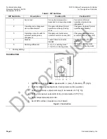
Construction
1
Standby mode selector /fan speed switch: (Low),
(Medium),
(High).
2
LEDs for indicating Heating mode, Cooling mode and fan operation.
3
Setting for minimum setpoint limit stop (in increments of 2°F [1°C]).
4
Setting for maximum setpoint limit stop (in increments of 2°F [1°C]).
5
Room temperature setpoint knob.
6
Set of DIP switches (mounted on circuit board).
Figure 4. Construction.


