Document No. 545-404
Installation Instructions
December 17, 2003
Information in this publication is based on current specifications. The company reserves the right to make changes in specifications and
models as design improvements are introduced. Other product or company names mentioned herein may be trademarks of their respective
owners. © 2003 Siemens Building Technologies, Inc.
Siemens Building Technologies, Inc.
1000 Deerfield Parkway
Buffalo Grove, IL 60089-4513
U.S.A.
Your feedback is important to us. If you have
comments about this document, please send
them to [email protected]
Document No. 545-404
Printed in the U.S.A.
Page 2 of 2
Installation
The termination block and point module contain
mechanical keys that prevent assembly of blocks
and modules of unlike voltages.
•
High voltage termination blocks are dark
gray and will only mate with high voltage
point modules.
•
Low voltage termination blocks are light gray
and will only mate with low voltage point
modules.
NOTE: High voltage termination blocks also have
the symbol printed next to the
termination block part number (PTX6.H).
CAUTION:
High Voltage (Class 1) PTMs must be placed
in the upper right corner of the panel. All other
PTMs must be on the left side of the panel or
below the high/low voltage wire barrier on the
right side.
1. Use the MBC/RBC layout sheet to determine the
correct block position number.
The block position number is printed on the
mounting rail label as 1A, 2A, etc. (Figure 2).
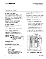
Figure 2. Installing a Termination Block.
2.
Remove the protective tape along the
perforations to uncover the slot where the
termination block attaches to the Module BUS
(M-BUS).
NOTE:
Leave the unused rails covered by the
protective tape until all termination
blocks are wired.
3. Align the termination block mounting hooks with
the edge of the mounting rail (
Figure 2).
4. Rotate the free end of the termination block into the
M-BUS rail.
5. Verify that the mounting guides on the
termination block are aligned with the mating M-
Bus rail slot (Figure 2).
6. Firmly press the termination block into the M-
Bus rail.
You will hear a light “click” when the termination
block is properly mounted.
7. Repeat Steps 1 through 6 until all termination
blocks have been installed.
The installation is now complete.
To Reposition or Remove a Termination Block
Remove the termination block from the mounting rail
by pushing and holding the release tab toward the
terminal screw end of the termination block while
rotating the block out of the M-BUS rail (Figure 3).
Figure 3. Removing a Termination Block.


