


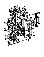


PRESSURE CONTROL
(B and C series only)
A capped potentiometer is located on the face
plate of the diaphragm pump. This potentiometer
is for pressure control or power to the pump
solenoid. Since the PolyBlend unit is equipped
with a 20 PSI backpressure/check valve, the
potentiometer should be set for full power or full
clockwise.
NOTE:
This is preset at the factory. In a case
where obvious over-pumping is present, this
potentiometer may be adjusted counter-
clockwise.
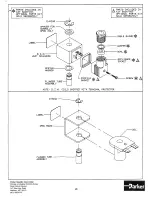
Liquifram (Diaphragm) Replacement
When replacing the Liquifram, valve balls, seal
rings and the injection check valve spring should
also be replaced.
1. Carefully depressurize, drain and
disconnect the pump discharge and suction lines.
Place the suction tubing into a container of
mineral oil. Turn the pump on to flush the head
assembly. Once the pump head has been flushed,
lift the suction tubing out of the mineral oil and
continue to pump air into the pump head until the
pump head is purged.
2. Start the pump. While running, set the
stroke knob to zero and turn the pump off.
NOTE:
See section on proper zeroing.
3. With the unit off, unscrew the Liquifram
by carefully grasping the outer edge of the
Liquifram and turning it counter clockwise.
Discard old Liquifram disk if so equipped (locate
behind the Liquifram) and check that the size
code matches the size code on the replacement
Liquifram (see illustration).
4. Reinstall the disk so alignment pin on the
disk (if present) seats in the recessed hole in the
EPU.
WARNING:
Take care not to scratch the Teflon
face of the new Liquifram.
5. Start the pump and turn the stroke knob to
the setting indicated on the Stroke Setting Chart
which matches the pump model number located
on the pump dataplate. With the pump stoking
(running), screw on the new Liquifram clockwise
until the center begins to buckle inward. Stop the
pump.
Liquifram Stroke Setting Chart
Pump Series
Stroke Knob Settings
A11 AA, B72, C72, 90%
C77
70%
6. Grasp the outer edge of the Liquifram
and adjust by screwing it in or out so that the
center of the Liquifram is flush with the outside
of the spacer edge (see illustration).
7. Once the Liquifram is properly
positioned, remount the pump head to the spacer
using the four (4) screws. Tighten in a crisscross
pattern. After one week of operation, recheck the
screws and tighten if necessary.
12
Summary of Contents for PolyBlend PB200-2
Page 17: ...15 ...
Page 18: ...16 ...
Page 19: ...17 ...
Page 20: ...18 ...
Page 21: ...19 ...
Page 22: ...20 ...
Page 24: ...200 D 007 ...
Page 26: ...MC 0101 24 ...
Page 28: ...Blank Page 26 ...
Page 30: ...OPD 0001 Post Dilution Static Mixer Assembly P N 5860001 28 ...
Page 32: ...Series AA7 Drive Assembly Exploded View Diagram 30 ...
Page 35: ...33 ...
Page 36: ...34 ...


