


2/4
Siemens Building Technologies
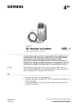
Air damper actuators GEB...1, rotary version
CM2N4621en
Landis & Staefa Division
16.03.2001
Type summary
GEB....
131.1E
132.1E
136.1E
331.1E
332.1E
336.1E
161.1E
163.1E
164.1E
166.1E
Control type
Three-position control
Modulating control
Operating voltage
AC 24 V
X
X
X
X
X
X
X
Operating voltage
AC 230 V
X
X
X
Positioning signal Y
DC 0...10 V
X
X
X
X
DC 2...10 V
X
X
DC 0...35 V with characteristic
function Uo,
∆
U
X
X
Position indicator
U = DC 0...10 V
X
X
X
X
Feedback potentiometer 1k
Ω
X
X
Self-adaptation of
rotary angle range
X
X
X
X
Auxiliary switches (two)
X
X
X
X
Rotary direction switch
X
X
X
X
Powerpack (two actuators,
tandem-mounted)
X
X
X
X
X
X
Functions
Type
GEB13..1 / GEB33...1
GEB16..1
Control type
Three-position control
Modulating control
Positioning signal with adjustable
characteristic function
DC 0...35 V with
Offset
Uo = 0...5 V and
span
∆
U = 2...30 V
Clockwise or counter-clockwise direction depends...
Rotary direction
…the type of control. With no power applied, the
actuator remains in the respective position.
...the DIL switch setting clockwise / counter-
clockwise
Position indication: Mechanical
Rotary angle position indication by using a position indicator.
Position indication: Electrical
The feedback potentiometer can be
connected to external voltage to indicate
the position.
Position indicator:
Output voltage U = DC 0...10 V is generated
proportional to the rotary angle. U depends on the
rotary direction of the DIL switch.
Auxiliary switch
The switching points for auxiliary switches A and B can be set independent of each other
in increments of 5° within 0° to 90°.
Self-adaptation of
rotary angle range
When self-adaptation is active, the actuator
automatically determines the mechanical end
positions of the rotary angle range and maps the
characteristic function (Uo,
∆
U) to the calculated
rotary angle range.
Powerpack
Mounting two of the same actuator types on the
same damper shaft may result in a double torque.
Not permitted.
Rotary angle limitation
The rotary angle of the shaft adapter can be limited mechanically at increments of 5°.
Ordering
Potentiometer and auxiliary switches cannot be added in the field. For this reason,
order the type that includes the required options.
Individual parts such as position indicator and other mounting materials for the actuator
are not mounted on delivery.
Note
Delivery