Installation, connecting up, commissioning
3.3 Connecting up the device
LOGO! CMR2020, LOGO! CMR2040
40
Operating Instructions, 10/2016, C79000-G8976-C356-03
Requirements for the cable
Requirements for the network cable:
●
Use a shielded Ethernet cable for connection to the Ethernet interface.
●
To minimize electromagnetic disturbances use a pair of shielded, twisted Ethernet cables
(category 5) and a shielded RJ-45 plug at both ends.
3.3.2
Inputs and outputs
Refer to the technical specifications for the load capabilities of the inputs and outputs.
Ideally, use a debounced switch to connect to a LOGO! CMR input.
Inputs and outputs
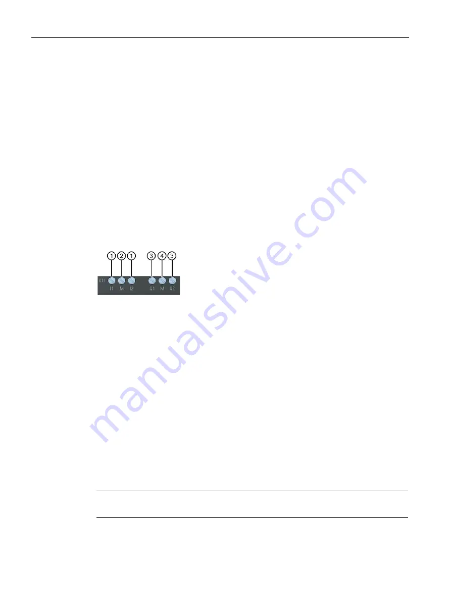
The CMR has two digital inputs and two digital outputs. The connecting terminals are on the
underside of the device.
①
Inputs I1 and I2
②
Reference potential inputs
③
Outputs Q1 and Q2
④
Reference potential outputs
Inputs I1 and I2
The connecting terminals of the inputs are labeled I1 and I2. The reference potential for both
inputs is "M".
Using the Web user interface, you can assign any function to each input, for example
triggering an alarm SMS message, see section Monitoring (Page 107).
The status of an input can also be read using SMS.
Outputs Q1 and Q2
The connecting terminals of the outputs are labeled Q1 and Q2. The reference potential for
both outputs is "M".
You can assign any function to each output using the Web user interface see section
Monitoring (Page 107). The outputs can be set and reset using SMS messages.
Note
Remember the electrical load capacity of the output.
You will find the electrical values for the inputs and outputs in the section Technical
specifications (Page 141).


