background image

 Installation  

en

19

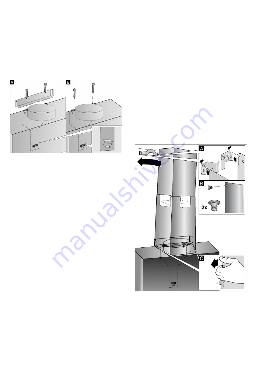
Wall-mounting the appliance and levelling it

1.

First remove the protective film from the back of the 

appliance and, following installation, remove the rest 

of the film.

2.

When mounting the appliance, ensure that it 

engages properly with the mounting supports.

3.

If required, the appliance can be moved to the right 

or to the left.

4.

Firmly tighten the screws for the mounting supports. 

Hold the bracket firmly when doing so. 

¨

5.

If no duct is to be fitted, screw in the two locking 

screws without the bracket. 

©

Connecting the pipes

If the extractor hood is to be operated in exhaust-air 

mode, the pipes must be connected. If the extractor 

hood is to be operated in air-recirculation mode, an 

optional accessory must be fitted. To do this, refer to 

the installation instructions provided.

Note: 

If an aluminium pipe is being used, smooth the 

connection area beforehand.

Exhaust air pipe, dia. 150 mm (recommended size)

Fit the exhaust air pipe directly to the air-pipe connector 

and seal the joint.

Exhaust air pipe, dia. 120 mm

1.

Fit the reducing connector directly to the air-pipe 

connector.

2.

Attach the exhaust air pipe to the reducing 

connector. 

3.

Use suitable means to seal both joints.

Attaching the flue duct

If the extractor hood is to be operated in exhaust-air 

mode, a flue duct must be fitted. 
The flue duct does not need to be fitted for air-

recirculation mode.

:

Warning

Risk of injury!

From sharp edges during installation. Always wear 

protective gloves while installing the appliance.

:

Warning

Risk of electric shock!

Components inside the appliance may have sharp 

edges. These may damage the connecting cable. Do 

not kink or pinch the connecting cable during 

installation.

1.

Separate the flue duct sections by removing the 

adhesive tape. 

2.

Remove the pieces of protective film from both flue 

duct sections.

3.

Push one flue duct section into the other.

Notes

– To prevent scratches, lay paper over the edges of 

the outer flue duct section to protect the surface.

– The slots of the inner flue duct section point 

downwards.

4.

Place flue ducts sections on the appliance.

5.

Slide the inner flue duct section upwards, attach it to 

the left and right sides of the retaining bracket, and 

then slide it down to engage it. 

¨

6.

Screw the flue duct section to the sides of the 

retaining bracket using two screws. 

©

7.

Clip the lower flue duct section in at the retaining 

bracket. The connection cable must not be 

damaged. 

ª

Note: 

If an air-recirculation optional accessory has been 

fitted and the extractor hood is to be operated without a 

flue duct, the cable must be wound onto the connector.

Summary of Contents for LC91KWP60

Page 1: ...Register your product online siemens home bsh group com welcome en QVWUXFWLRQV IRU LQVWDOODWLRQ DQG XVH Extractor hood ...

Page 2: ...llation location This appliance is intended for domestic use and the household environment only The appliance is not intended for use outside Do not leave the appliance unattended during operation The manufacturer is not liable for damage which is caused by improper use or incorrect operation This appliance is intended for use up to a maximum height of 2000 metres above sea level This appliance ma...

Page 3: ...ndows incoming exhaust air wall boxes or by other technical means In any case consult your responsible Master Chimney Sweep He is able to assess the house s entire ventilation setup and will suggest the suitable ventilation measures to you Unrestricted operation is possible if the vapour extractor hood is operated exclusively in the circulating air mode Warning Risk of fire Fatty deposits in the g...

Page 4: ...t the after sales service Risk of electric shock Incorrect repairs are dangerous Repairs may only be carried out and damaged power cables replaced by one of our trained after sales technicians If the appliance is defective unplug the appliance from the mains or switch off the circuit breaker in the fuse box Contact the after sales service Risk of electric shock Do not use any high pressure cleaner...

Page 5: ...modes OperatingmodesExhaust air mode Note The exhaust air must not be conveyed into a functioning smoke or exhaust gas flue or into a shaft which is used to ventilate installation rooms which contain heat producing appliances Before conveying the exhaust air into a non functioning smoke or exhaust gas flue obtain the consent of the heating engineer responsible If the exhaust air is conveyed throug...

Page 6: ...nel Note After approx 6 minutes the extractor hood automatically switches back to fan setting 3 Switching off If you want to end intensive mode before the preset time expires touch the A symbol to select the fan setting you require Boost function Switching on Touch the symbol Note After approximately 20 seconds the extractor hood automatically switches back to the fan setting that was set beforeha...

Page 7: ...or air recirculation mode For air recirculation mode the electronic controller must be switched over accordingly The extractor hood must be connected and switched off Touch and hold the and symbols at the same time until 2 lights up for air recirculation mode filters that cannot be regenerated Repeatedly touching and holding this button combination makes 3 light up for air recirculation mode filte...

Page 8: ...seconds the extractor hood automatically switches back to the fan setting that was set beforehand Switching off If you want to end the Boost function before the preset time expires touch the symbol powerBoost position On some appliances the glass front can be adjusted to an intermediate position powerBoost position The powerBoost position can be used for eliminating particularly strong cooking sme...

Page 9: ...ely 3 seconds when the fan is switched off An audible signal will sound as an acknowledgement When the signal tone is activated will be lit Switching off Touch and hold the and symbols at the same time for approximately 3 seconds when the fan is switched off An audible signal will sound as an acknowledgement When the signal tone is deactivated will be lit 2Cleaning and maintenance Cleaningandmaint...

Page 10: ...y water Clean the filters with a brush and then rinse them thoroughly Leave the metal grease filters to drain on an absorbent material In the dishwasher Note Slight discolouration may occur if the metal grease filters are cleaned in the dishwasher This discolouration has no effect on the performance of the metal grease filters Use normal domestic dishwashing detergents Do not clean heavily soiled ...

Page 11: ...les replaced by one of our trained after sales technicians If the appliance is defective unplug the appliance from the mains or switch off the circuit breaker in the fuse box Contact the after sales service Malfunction table LED lights Defective LED lights may be replaced by the manufacturer their customer service or a qualified technician electrician only Warning Risk of injury The light emitted ...

Page 12: ... in the accessory E no FD no After sales serviceO GB 0344 892 8999 Calls charged at local or mobile rate IE 01450 2655 0 03 per minute at peak Off peak 0 0088 per minute Z Nr FD E Nr Type Accessories Order number Starter set for air recirculation mode flat hood with chimney Easy change filter for starter set LZ10AFU00 LZ10AFA00 Starter set for air recirculation mode flat hood without chimney Easy ...

Page 13: ...erated in air recirculation mode an optional accessory must be fitted To do this refer to the installation instructions provided The flue duct does not need to be fitted for air recirculation mode For additional optional accessories refer to the installation instructions provided The surfaces of the appliance are sensitive Avoid damaging them during installation PLQ PP PLQ PP PD PP PLQ PP PLQ PP P...

Page 14: ...on location The surfaces of the appliance are easily damaged Avoid damaging them during installation The width of the extractor hood must correspond at least with the width of the hob For the installation observe the currently valid building regulations and the regulations of the local electricity and gas suppliers Warning Risk of fire Fatty deposits in the grease filter may catch fire The specifi...

Page 15: ...al vacuum in the place where the heat producing appliance is installed does not exceed 4 Pa 0 04 mbar This can be achieved when the air needed for combustion is able to enter through openings that cannot be sealed for example in doors windows incoming exhaust air wall boxes or by other technical means In any case consult your responsible Master Chimney Sweep He is able to assess the house s entire...

Page 16: ...l KGeneral information GeneralinformationChecking the wall The wall must be level vertical and adequately load bearing The depth of the bore holes must be the same length as the screws The wall plugs must have a secure grip The enclosed screws and wall plugs are suitable for solid brickwork Suitable fasteners must be used for other structures e g plasterboard porous concrete poroton bricks The max...

Page 17: ...hood should be positioned and lightly mark where the lower edge of the appliance should be on the wall Determine where the middle should be based on the hob Note We recommend fitting the extractor hood such that the lower edge of the glass screen is in line with the lower edges of the adjacent wall hung cabinets Make sure that the specified safety clearances from the hob are complied with 2 Place ...

Page 18: ...hout a flue duct Installation Screw in the mounting supports for the extractor hood until they are hand tight use a spirit level to level the appliance and then screw the mounting supports in fully PP PP PP PP PP PP PP PP PP PP PP PP PP PP PP PP PP PP PP PP ...

Page 19: ...ints Attaching the flue duct If the extractor hood is to be operated in exhaust air mode a flue duct must be fitted The flue duct does not need to be fitted for air recirculation mode Warning Risk of injury From sharp edges during installation Always wear protective gloves while installing the appliance Warning Risk of electric shock Components inside the appliance may have sharp edges These may d...

Page 20: ...BSH Hausgeräte GmbH Carl Wery Straße 34 81739 München GERMANY 9001158922 9001158922 970606 siemens home bsh group com 0DQXIDFWXUHG E 6 DXVJHUlWH PE XQGHU 7UDGHPDUN LFHQVH RI 6LHPHQV ...

Reviews: