
Siemens SpA
Building Technologies
CE1N7609e / 11-07-2008
2/4
___________________________________________________________________________________________
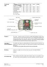
Outputs
Detector
GREEN
LED
YELLOW
LED
RED
LED
RELAY BUZZER
OFF (no power supply)
OFF
OFF
OFF
OFF
OFF
Preheating (60s)
ON
ON
OFF
OFF
OFF
Normal operation
ON
OFF
OFF
OFF
OFF
Gas alarm
ON
OFF
ON
ON
ON
Sensing element fault
ON
ON
OFF
OFF
OFF
ON = lit / activated
OFF = off / deactivated
____________________________________________________________________________________________
____________________________________________________________________________________________
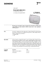
The LYA14... detectors consist of two parts: an ABS self-extinguishing housing with a
removable cover and a part containing the electronic circuit, terminals and sensing element.
There are three LEDs on the cover: green, yellow and red for indicating normal operation,
preheating/sensor failure and gas alarm, respectively. The detectors are factory-calibrated
to assure intervention at gas concentrations below the dangerous limit.
____________________________________________________________________________________________
The installer must respect the existing standards concerning the electrical connections. The
detector must be directly connected to the mains (without any switches) and be permanently
powered on.
The detectors must be replaced after 5 years from the date of installation.
_____________________________________________________________________________________________
Indicate the complete item code of the detector (see also “AVAILABLE MODELS”).
LYA14.G
LYA14.P
____________________________________________________________________________________________
Read carefully the instructions provided with the detector. Keep it in a safe place for future
use. Respect all the existing regulations concerning the installation of electrical equipment.
Functional
table
Features
Installation
recommendations
Ordering
Commissioning
electromechanical buzzer
sensing element
230VAC power supply
terminals
green LED (power supply)
screw for cover lock
yellow LED
(preheating / sensing elem. fail)
red LED (gas alarm)
openings for
cable input
hole for wall mounting
hole for wall mounting
relay output