7
For the installer
■
An all-pole isolating switch with a contact gap of at least
3 mm must be present in the installation circuit. This is not
necessary if the appliance is connected by a plug that is
accessible to the user.
■
Electrical safety: The cooker corresponds to safety class I
and may only be used in conjunction with a safety earth
terminal.
■
A type H 05 VV-F or equally rated lead must be used to
connect the appliance.
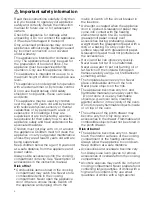
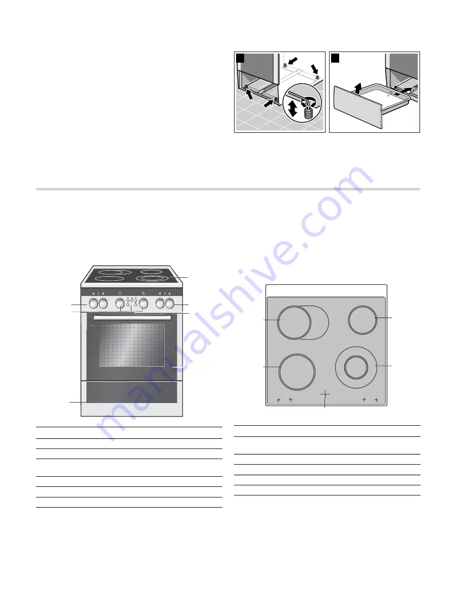
Levelling the cooker
Always place the cooker directly on the floor.
1.
Pull out the plinth drawer and lift it up and out.
There are adjustable feet at the front and rear on the inside of
the plinth.
2.
Use an Allen key to raise or lower the adjustable feet as
necessary until the cooker is level (picture A).
3.
Push the plinth drawer back in (picture B).
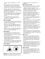
Wall fixing
To prevent the cooker from tipping over, you must fix it to the
wall using the enclosed bracket. Please observe the installation
instructions for fixing the oven to the wall.
Your new cooker
Here you will learn about your new cooker. We will explain the
control panel, the hob and the individual operating controls.
You will find information on the cooking compartment and the
accessories.
General information
The design depends on the respective appliance model.
Control knobs
The control knobs can be pushed in and remain pressed down
when they are in the "out" position. Press down on the control
knob again to release it back up.
Cooking area
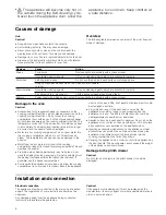
Here is an overview of the control panel. The design depends
on the respective appliance model.
%
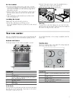
$
Explanations
1
Hob
2
Hotplate knob
3
Function selector, operating switches and display
panel, temperature selector
4
Appliance cooling
5
Oven door
6
Plinth drawer
Explanations
1
Hotplate 17 cm or extended cooking zone 17x26
cm
2
Hotplate 14,5 cm
3
Hotplate 18 cm
4
Dual-circuit hotplate 21 and 12 cm
5
Residual heat indicator


