background image

User Manual  SICLOCK GPS1000 

18 

Version 1.0 

Order number 2XV9450-1AR82-BA 


SICLOCK is a registered 
trademark of SIEMENS AG. 

 
Technical  data  is  subject  to  change.  We  have  checked 
the contents of this manual for agreement with the hard-
ware  or  software  described.  Since  deviations  cannot  be 
entirely precluded, we cannot guarantee full agreement. 

The reproduction, transmission or use of this document 
or its contents is not permitted without express written 
authority. Offenders will be liable for damages. 

All rights, including rights created by patent grant of a 
utility or design are reserved. 

© Siemens AG 2005 


Summary of Contents for GPS1000 2XV9450-1AR82

Page 1: ...SICLOCK GPS1000 2XV9450 1AR82 Betriebsanleitung User Manual Deutsch 1 0 Stand Oktober 2005 English D GB Bestell Nr 2XV9450 1AR82 BA ...

Page 2: ...Ansprechpartner örtliche Siemens Niederlassung Bestellungen örtliche Siemens Niederlassung Herausgeber Siemens AG I S EDM Frauenauracher Straße 98 D 91056 Erlangen SICLOCK Hotline 49 9131 7 2 88 66 Fax 49 9131 18 8 06 04 E Mail siclock siemens com Internet http www siemens de siclock Technische Änderungen vorbehalten Siemens AG 2005 ...

Page 3: ... 2 Vorgehensweise bei der Montage 13 5 Anhang 15 5 1 Technische Daten 15 5 2 Bestell Daten 15 5 3 Genauigkeiten 16 5 4 Antennenfußgestell 16 Abbildungsverzeichnis Abbildung 1 Frontansicht GPS1000 PS 5 Abbildung 2 Installationsschema für SICLOCK TM und PC ohne Blitzschutzmodul 6 Abbildung 3 Installationsschema für SICLOCK TM und PC mit Blitzschutzmodul 7 Abbildung 4 Installationsschema für SICLOCK ...

Page 4: ... Elektromagnetische Störfelder aus der Anlage können außer Acht gelassen werden da die Betriebsfrequenz von GPS1000 oberhalb des Industrie Störnebels liegt 2 Montagebohrungen für Antennenfußgestell anzeichnen bohren und Dübel setzen 3 Bohrung für das Anschlusskabel setzen bei Wandmontage am besten in der Mitte unter der Fußplatte 4 Antenne entsprechend der Abbildung 9 bzw Abbildung 10 zusammenbaue...

Page 5: ...nn es bis zu 30 Min und mehr dauern bis überhaupt Satelliten in diesem Fenster auftau chen und der Initialisierungsvorgang dauert dann um diese Zeitdauer entsprechend länger Während des Initialisierungsvor gangs blinkt die gelbe LED Sig kontinuierlich im 2 Sekundentakt Lebenszeichen Danach beginnt der Normalbetrieb in dem ständig simulierte DCF77 Telegramme mit Greenwich Meantime von der Anten ne ...

Page 6: ...dung 2 zeigt schematisch den Anschluss von GPS1000 an SICLOCK TM oder einen PC ohne Blitzschutz Die als Foto abgebildeten Teile und grauen Kabel befinden sich im Lieferumfang des Gesamtpakets SICLOCK GPS1000 Die roten Kabel müssen bauseits zur Verfügung gestellt werden Abbildung 2 Installationsschema für SICLOCK TM und PC ohne Blitzschutzmodul ...

Page 7: ...nd grauen Kabel befinden sich im Lieferumfang des Gesamtpakets SICLOCK GPS1000 mit Ausnahme des Blitzschutzmoduls Die roten und grünen Kabel müssen bauseits zur Verfügung ge stellt werden Das Blitzschutzmodul sollte in unmittelbarer Nähe der Eintrittsstelle ins Gebäude des von der Antenne kommenden Kabels montiert werden IN und OUT beachten Wichtig Das grün dargestellte an der Hutschiene angeschlo...

Page 8: ...eten Teile und grauen Kabel befinden sich im Lieferumfang des Gesamtpakets SICLOCK GPS1000 Die roten Kabel müssen bauseits zur Verfügung gestellt werden Abbildung 4 Installationsschema für SICLOCK TS ohne Blitzschutzmodul Erforderliche Parametrierung bei SICLOCK TS 1 Eingang E1 auf GPS1000 einstellen Siehe auch Betriebsanleitung SICKLOCK TS 2 Zeitzone entsprechend des Standortes in Bezug auf GMT e...

Page 9: ...snahme des Blitzschutzmoduls Die roten und grünen Kabel müssen bauseits zur Verfügung gestellt werden Das Blitzschutzmodul sollte in unmittelbarer Nähe der Eintrittsstelle ins Gebäude des von der Antenne kommenden Kabels montiert werden Wichtig Das grün dargestellte an der Hutschiene angeschlossene Erdungskabel Querschnitt 25 qmm oder mehr muss unbedingt auf kürzestem Weg möglichst geradlinig an e...

Page 10: ...zwischen der Gewitterwolke und dem Einschlagspunkt nicht kontinuierlich mit konstanter Geschwindigkeit zurücklegt sondern ruckartig in Intervallen mit durchschnittlich 20 bis 40 Metern Länge Zwischen diesen Blitz Fortschritts Abschnitten liegen jeweils Wartepunkte von einigen Mikrosekunden in denen weitere Energie aufgebaut wird siehe Abbildung 6 Die möglichen Standorte der nachfolgenden Wartepunk...

Page 11: ...n die Blitzkugel in Gedanken über alle Flächen und Kanten des zu untersuchenden Gebäudes rollt siehe Abbildung 7 und Abbildung 8 Überall dort wo die Blitzkugel Flächen oder Kanten berührt liegen einschlaggefährdete Bereiche rot dargestellt Abbildung 7 Ermittlung der potentiellen Blitzeinschlagsbereiche normales Gebäude Abbildung 8 Ermittlung der potentiellen Blitzeinschlagsbereiche Industriegebäud...

Page 12: ...eich montieren Nie im roten Bereich 2 Antennenkabel auf kürzestem Weg ins Gebäudeinnere führen 3 Antennenkabel grundsätzlich rechtwinklig zu in der Nähe befindlichen Blitzablei tern verlegen da dann die Induktionswirkung am geringsten ist 4 Den 2m Abstand zu Blitzableitern auch bei im Inneren des Gebäudes verlegten Antennenkabeln einhalten da bei vielen Wänden immer noch die Durchschlagsgefahr dur...

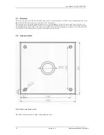
Page 13: ...hen d h sie sollte nicht im Schatten von großen Gebäuden oder unter überstehenden Gebäudeteilen etc stehen Günstige Standorte für die Antenne sind z B auf einem Flachdach Günstige Standorte im Innern des Gebäudes finden sich unten an großen Fensterfronten oder unter Lichtkuppeln 4 2 Vorgehensweise bei der Montage Den Zusammenbau der Antenne für Wand oder Flachdachmontage zeigen die nachstehenden A...

Page 14: ...skant Gewindestifte links und rechts angezogen Bei der Wandmontage Abb 10 wird das Anschlusskabel des Antennenkopfes 1 rechtwinklig durch den Würfel 2 gesteckt der Antennenkopf Stutzen bis zum Anschlag in die Öffnung des Würfels geschoben und mit den 2 zugehörigen Innensechskant Gewindestiften links und rechts leicht angezogen Nun wird das Anschlusskabel von oben durch das Antennenfußgestell 5 ges...

Page 15: ...l 160 x 630 x 160 mm Antennenkopf 160 x 85 x 80 mm Schutzart IP 65 Betriebstemperatur 40 C bis 60 C Montage Antennen Gestell mit 4 Schrauben in jeder Lage montier und ausrichtbar SICLOCK GPS1000 PS Stromversorgung für Betrieb mit SICLOCK TM oder PC Stromversorgung 24 240V AC DC Leistungsaufnahme 5 W Speisung GPS1000 48V 40mA DCF77 Ausgänge 2 SICLOCK TM PCON EOPC TTY 20mA PC COM Schnittstelle RS232...

Page 16: ... aufeinanderfolgender Impulse die absolute Genauigkeit den Versatz zur Atomuhr wel che das gesamte GPS System speist Auf die absoluten Zeiten muss bei Verbindung zu weniger als vier Satelliten noch die Zeitungenauig keit von 20ms bis 50ms addiert werden welche aus der Signallaufzeit vom Satelliten zur Erde resultiert und in diesem Fall vom Empfänger nicht korrigiert werden kann Bei einer Verbindun...

Page 17: ...Betriebsanleitung SICLOCK GPS1000 Bestellnummer 2XV9450 1AR82 BA Version 1 0 17 Notizen ...

Page 18: ...ng gilt nicht als Zusicherung von Ei genschaften Technische Daten und Abbildungen sind unverbindlich für die Lieferung Weitergabe sowie Ver vielfältigung dieser Unterlage Verwertung und Mittei lung ihres Inhaltes ist nicht gestattet soweit nicht aus drücklich zugestanden Zuwiderhandlungen verpflichten zu Schadensersatz Alle Rechte vorbehalten insbesondere für den Fall der Patenterteilung oder GM E...

Page 19: ...SICLOCK GPS1000 Radio Clock 2XV9450 1AR82 User Manual 1 0 Revision October 2005 Order No 2XV9450 1AR82 BA ...

Page 20: ...angen Contact person local Siemens branch Orders local Siemens branch Published by Siemens AG I S EDM Frauenauracher Straße 98 D 94056 Erlangen SICLOCK Hotline 49 9131 7 28866 Fax 49 9131 7 22977 E Mail siclock siemens com Internet http www siemens com siclock Technical subject to change without notice Siemens AG 2005 ...

Page 21: ...ion location 13 4 2 Mounting procedures 13 5 Appendix 15 5 1 Technical data 15 5 2 Ordering data 15 5 3 Precision 16 5 4 Antenna stand 16 Index of Illustrations Fig 1 Front view GPS1000 PS 5 Fig 2 Installation diagram for SICLOCK TM and PC without lightning protection module 6 Fig 3 Installation diagram for SICLOCK TM and PC with lightning protection module 7 Fig 4 Installation diagram for SICLOCK...

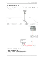
Page 22: ...tic interference fields from the plant do not need to be taken into account as the operating frequency of GPS1000 is above the industrial interference level 2 Mark the drill holes for installing the antenna stand drill and insert dowels 3 Make the bore hole for the connecting cable for wall mounting preferably in the middle underneath the base plate 4 Assemble the antenna according to figures 9 an...

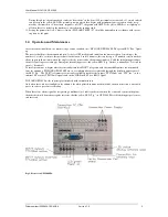
Page 23: ... more until sat ellites appear in this window when the angle to the sky perceived by the antenna is under 90 and the initializing procedure therefore lasts longer accordingly During the initializing process the yellow LED Sig flashes continually at 2 second in tervals heartbeat Normal operation now begins whereby constantly simulated DCF77 telegrams with Greenwich Meantime are transmitted from the...

Page 24: ...hematic diagram of the connection of GPS1000 to SICLOCK TM or to a PC without lightning protection The parts illustrated in photos and the grey cable are included in the scope of delivery of the complete package SICLOCK GPS1000 The red cables must be provided on site Fig 2 Installation diagram for SICLOCK TM and PC without lightning protection module ...

Page 25: ...y for the complete package SICLOCK GPS1000 with the exception of the lightning protection module The red and green cables must be made available on site The lightning protection module should be installed in the building as near as possible to where the cable coming from the antenna enters the building Please pay attention to IN and OUT Important It is absolutely essential that the earth cable sho...

Page 26: ...s illustrated in photo and the grey cable are included in the scope of delivery for the complete package SICLOCK GPS1000 The red cable must be made available on site Fig 4 Installation diagram for SICLOCK TS without lightning protection module Parametering required for SICLOCK TS 1 Set input E1 to GPS1000 See also operating manual SICLOCK TS 2 Set time zone according to the location in relation to...

Page 27: ... the lightning protection module The red and green cables must be made avail able on site The lightning protection module should be installed in the building as near as possible to where the cable coming from the antenna enters the building Important It is absolutely essential that the earth cable shown in green and connected to the DIN rail cross section 25 sq mm or more is connected in the short...

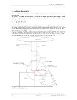
Page 28: ...e distance between the storm cloud and the point of striking at a continuous and constant speed but travels intermittently at intervals on average of 20 to 40 meter in length Between these lightning advancing distances there are holding points of a few microseconds during which time further energy is built up see Fig 6 The possible locations of the subsequent holding points lie within a sphere her...

Page 29: ...ple way by conjuring up a mental picture of the ball of lightning rolling over all the surfaces and edges of the building to be examined see Fig 7 and Fig 8 All areas where the ball of lightning touches surfaces or edges are in danger of being struck by lightning shown in red Fig 7 Determination of potential areas where lightning could strike normal buildings Fig 8 Determination of potential areas...

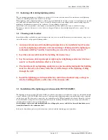
Page 30: ... 7 and Fig 8 and in the green area Never in the red area 2 Lead the antenna cable inside the building the shortest way 3 Lay the antenna cable in principle at right angles to lightning conductors which are nearby as then the induction effect is at its lowest 4 The 2m distance from lightning conductors to antenna cables laid inside the building must be enforced as for many walls there is still a da...

Page 31: ...n The antenna should see as much sky as possible i e it should not be overshadowed by large buildings or stand un derneath parts of buildings etc A preferred location for the antenna for example would be on a flat roof Preferred locations inside a building are underneath large window frontages or under glass domes 4 2 Mounting procedures The following illustrations show the assembly of the antenna...

Page 32: ...he two hexagonal socket set screws are then tightened gently on the left and right For wall mounting Fig 10 the connecting cable of the antenna head 1 is inserted through the cube 2 at a right angle the an tenna head support is pushed into the opening of the cube as far as it will go and the two hexagonal socket set screws gently screwed tight on the left and right Now the connecting cable is inse...

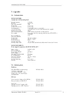
Page 33: ...x 80 mm System of protection IP 65 Operating temperature 40 C to 60 C Mounting antenna stand can be mounted and directionally adjusted with 4 screws in all locations SICLOCK GPS1000 PS Power supply for operation with SICLOCK TM or PC Supply voltage 24 240V AC DC Power consumption 5 W Power supply GPS1000 48V 40mA DCF77 outputs 2 SICLOCK TM PCON EOPC TTY 20mA PC COM Interface RS232_ Dimensions WxHx...

Page 34: ... of two sequential impulses the absolute precision the offset to the atom clock which supplies the whole GPS system For connection to fewer than four satellites the time precision of 20ms to 50ms which results from the signal running time from satellites to the earth must be added to the absolute times and in this case cannot be corrected by the receiver For connection to four satellites there is ...

Page 35: ...User Manual SICLOCK GPS1000 Order numberr 2XV9450 1AR82 BA Version 1 0 17 Notes ...

Page 36: ...al for agreement with the hard ware or software described Since deviations cannot be entirely precluded we cannot guarantee full agreement The reproduction transmission or use of this document or its contents is not permitted without express written authority Offenders will be liable for damages All rights including rights created by patent grant of a utility or design are reserved Siemens AG 2005...

Reviews: