50
FLUDEX 4612 en
Operating instructions 10/2017
10.6
Disassembling the FLUDEX coupling
For detailed part designations, see section 11.
FLUDEX couplings should as far as possible be repaired at the manufacturer’s works.
Before disassembly the housing parts must be marked on the flange in their positions relative to one
another.
The housing parts of the main coupling, the shell (101) and the cover (102) are joined at the outer flange
by screws (130) and nuts (131). For disassembly these screws must first be removed.
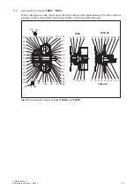
To pull off the shell and cover, a pressure spindle with a bridge and pulling screws must be applied as
shown in figure 17. The pressure acts on the end face of the shaft. The pulling screws are inserted in the
flange threads of the shell or cover.
5
4
3
1
2
Fig. 17:
Disassembling the FLUDEX coupling
1
Shaft
2
Shell (101)
3
Drawing bolts
4
Pressure spindle
5
Bridge
After the shell and cover are pulled off, the internal parts (rolling bearings, shaftsealing rings, etc.) will be
accessible. The sealing elements should be replaced every time the coupling is disassembled.
The rolling bearings must be checked and may be used again if they are found to be in order.
Summary of Contents for FLENDER FLUDEX FNA
Page 2: ......


