Features and Functions
03/03
CP 243-1 IT
J31069-D0429-U001-A0-7618
44
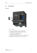
2.8 Indicators:
Front
LEDs
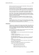
Fig. 4 Front with the LEDs
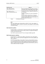
There are 5 LED indicators on the front.
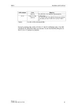
LED Indicator
Color
Meaning
Red, continuously
on
System error:
On when an error has occurred
SF
Red, flashing
System error:
Flashing (approx. once per second) when configura-
tion is incorrect or no BOOTP server could be found
LINK Green,
continu-
ously on
Connection via the RJ45 interface:
Ethernet connection is established.
RX/TX
Green, flickering
Ethernet activity:
Data are received or sent via Ethernet.
Note
:
A packet received via Ethernet must not always be
intended for the CP 243-1 IT. The CP 243-1 IT first
accepts all packets transmitted via Ethernet and
then decides whether the packet is intended for it-
self.
The RX/TX-LED flashes even when the Ethernet
cable is disconnected as soon as the CP 243-1 IT
attempts to send a packet.
RUN Green,
continu-
Ready for operation:
Summary of Contents for CP 243-1 IT
Page 46: ...Installation and Commissioning 03 03 CP 243 1 IT J31069 D0429 U001 A0 7618 46 ...
Page 94: ...Programming 03 03 CP 243 1 IT J31069 D0429 U001 A0 7618 94 ...
Page 106: ...Diagnosis 03 03 CP 243 1 IT J31069 D0429 U001 A0 7618 106 ...
Page 120: ...Technical Data 03 03 CP 243 1 IT J31069 D0429 U001 A0 7618 120 ...
Page 130: ...Example 03 03 CP 243 1 IT J31069 D0429 U001 A0 7618 130 ...

