


Siemens Industry, Inc. 5300 Triangle Parkway, Norcross, GA 30092
A5E31166447A-002
Auxiliary Contact
A maximum of two auxiliary units can be installed in the re
-
cesses of each contactor (see Fig. 5 for location and bottom of
Table 4 for the auxiliary units catalog numbers and their contact
configuration). Auxiliary units mount by means of spring clip
and retainer screw. To remove the unit rotate the retainer screw
several times (counter-clockwise) and then slide the auxiliary
contact unit out of the recess.
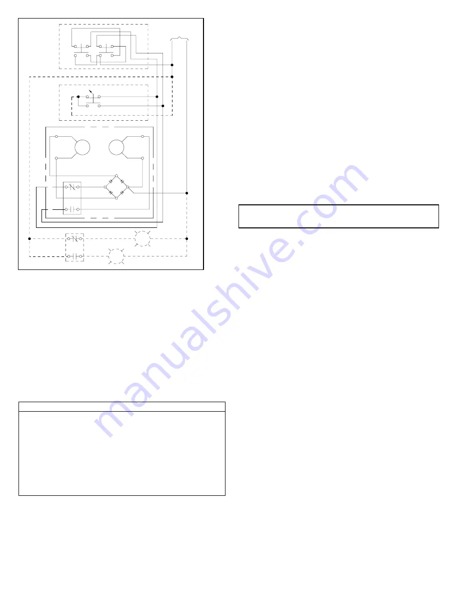
Fig. 2 Connection Diagram for Common/Separate Control
with Momentary Pushbutton or ON-OFF Selector
Switch
Table 3 - Coil
Voltage
VAC
Freq.
Hz
Part Number
2-4 Pole 5 Pole
24
60 Hz
CLMC4C024
CLMC5C024
110/120
50/60 Hz
CLMC4C120
CLMC5C120
208
60 Hz
CLMC4C208
CLMC5C208
220/240
50/60 Hz
CLMC4C240
CLMC5C240
277
60 Hz
CLMC4C277
CLMC5C277
440/480
50/60 Hz
CLMC4C480
CLMC5C480
550/600
50/60 Hz
CLMC4C600
CLMC5C600
CAUTION -
All control wiring for contactor operation must only be made to
the coil isolation contact terminals #2, #3 and L2 terminal con-
nection points. Wiring made to any other terminal points will
burn out the coil and diode. If a coil burnout occurs, both the
coil and the diode must be replaced.
Coil Replacement
–
refer to Figure 1, Table 3.
Loosen the two screws at each side of the upper base and re
-
move the wire connections. Loosen the assembly screws (1).
Pull the loosened upper base structure (2) forward. Unplug
the coil (3) from the upper base, plug in a new coil and re
-
place the upper base structure while depressing the kick-out
springs (4) to ensure they set in the molded seats in the cross-
bar (5). Reconnect the four coil leads. Tighten the assembly
screws referring to Table 2. Mechanically operate the unit to
ensure there is no binding of the crossbar.
Contact Inspection
–
refer to Figure 1
Loosen the two arc chute screws (6) located immediately
above and below the nameplate and remove the arc chute
(7). The contacts (8) are visible. Re-tighten the screws per
Table 2.
Contact Wear and Replacement –
refer to Figure 1,
Table 4.
CAUTION: Install arcbox prior to energization
Contacts are designed for a long service life based on a spe
-
cific electrical load under normal service and environmental
conditions. If any one of these factors is altered, a shorter ser
-
vice life or a breakdown will result. Contactors are subject to
both mechanical and electrical wear during their operation. In
most cases mechanical wear is insignificant. The erosion of
the contacts is due to electrical wear. During arcing, material
from each contact is vaporized and blown away from the useful
contacting surface.
Note:
When contact replacement is required, it is necessary
to replace both stationary and moving contacts plus moving
contact overtravel springs. After replacement, manually oper-
ate switch to be sure binding does not occur.
After removing the arc chute (7) and with replacement contacts
in hand, compress the overtravel spring (9) and remove the
moving contact (8) from the crossbar (5). Remove any power
connections. Remove screws (10) and lift out the stationary
contact carriers (11). The new contacts are then installed by
reversing the above procedure and referencing Table 2 for
torque specifications. Moving contacts should be free to move,
overtravel spring seated, and the crossbar free to move when
the arc chute is in position. Silver cadmium oxide contact but-
tons require NO dressing or lubrication during their life.
Magnet - Armature Assembly
Self alignment and permanent air gap features of the magnet
armature make replacement unnecessary. Mating pole face
surfaces should be kept clean.
OFF
ON
OFF
ON
VOLTAGE
CONTROL
(L1)
1
(L2)
X2
ON
OFF
( + )
( - )
BLACK
( + )
( - )
AC
AC
L2
RED
WHITE
CLMFCCK11
3
2
RE
D
CLMFCAK11
OFF
ON
RE
D
CLM CONTACTOR
All manuals and user guides at all-guides.com