7SR210 & 7SR220 Commissioning & Maintenance Guide
Page 32 of 82
© 2013 Siemens Protection Devices Limited
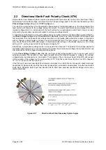
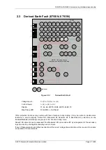
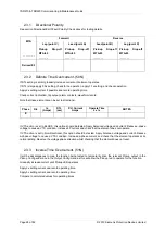
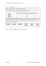
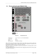
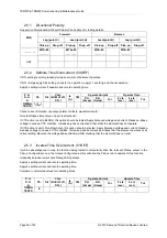
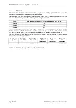
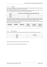
2.4.1 Directional Polarity
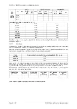
See section Directional Earth Fault Polarity Check above for testing details.
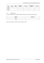
MTA
Forward
Reverse
Lag (point C)
Lead (point A)
Lead(point B)
Lag (point D)
Pick-up
Drop-off
Pick-up
Drop-off
Pick-up
Drop-off
Pick-up
Drop-off
………….
MTA-85
………..
MTA+85
…………
MTA-85
…………
MTA-85
………...
Measured
EF
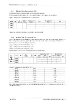
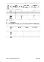
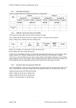
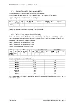
2.4.2 Definite Time Overcurrent..(67/50G)
If DTL setting is small, gradually increase current until element operates.
If DTL is large apply 0.9x setting, check for no operation, apply 1.1x setting, and check operation.
Apply 2x setting current if possible and record operating time.
Phase
Dir.
Is
(Amps)
DTL
(sec)
P.U. Current
Amps
Operate
Time
2 x Is
NOTES
I
4
Check correct indication, trip output, alarm contacts, waveform record.
Note that these elements can be set to directional.
If VTS action is set to BLOCK, this option should be tested. Apply balanced voltage and current. Reduce a-phase
voltage to cause a VTS condition. Increase a-phase current and check that the element does not operate.
If VTS action is set to Non-Directional, this option should be tested..Apply balanced voltage and current. Reduce
a-phase voltage to cause a VTS condition. Increase a-phase current and check that the element operates at its
normal setting. Reverse the voltage phase direction whilst checking that the element does not reset.
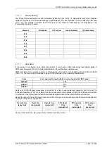
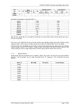
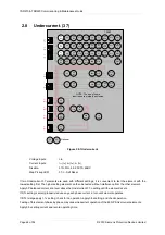
2.4.3 Inverse Time Overcurrent. (67/51G)
It will be advantageous to map the function being tested to temporarily drive the relevant Pickup output in the
Pickup Config
sub-menu in the
Output Config
menu as this will allow the Pick-up led to operate for the function.
Gradually increase current until Pickup LED operates.
Apply 2x setting current and record operating time.
Apply 5x setting current and record operating time.
Compare to calculated values for operating times.
Summary of Contents for Argus 7SR21
Page 1: ...Energy Management 7SR21 7SR22 Argus Overcurrent Relay Reyrolle Protection Devices ...
Page 2: ......
Page 4: ...Contents 7SR11 and 7SR12 Page 2 of 2 2018 Siemens Protection Devices Limited ...
Page 185: ...7SR210 Settings Guide Unrestricted 2018 Siemens Protection Devices Limited Page 61 of 61 ...
Page 277: ...7SR220 Settings Guide Unrestricted Page 72 of 107 2013 Siemens Protection Devices Limited ...
Page 382: ...7SR220 Technical Manual Chapter 4 Page 2 of 96 2017 Siemens Protection Devices Limited ...
Page 386: ...7SR220 Technical Manual Chapter 4 Page 6 of 96 2017 Siemens Protection Devices Limited ...
Page 398: ...7SR220 Technical Manual Chapter 4 Page 18 of 96 2017 Siemens Protection Devices Limited ...
Page 414: ...7SR220 Technical Manual Chapter 4 Page 34 of 96 2017 Siemens Protection Devices Limited ...
Page 466: ...7SR220 Technical Manual Chapter 4 Page 86 of 96 2017 Siemens Protection Devices Limited ...
Page 468: ...7SR220 Technical Manual Chapter 4 Page 88 of 96 2017 Siemens Protection Devices Limited ...
Page 470: ...7SR220 Technical Manual Chapter 4 Page 90 of 96 2017 Siemens Protection Devices Limited ...
Page 472: ...7SR220 Technical Manual Chapter 4 Page 92 of 96 2017 Siemens Protection Devices Limited ...
Page 643: ...Unrestricted ...

