Oper
a
tin
g
line
Oper
a
tin
g
level
Func
tio
n
Defaul
t
val
ue
Min
Max
Unit
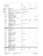
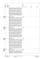
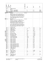
Flow switch consumers E24 ¦ Manual defrost E17 ¦
Common fault HP E20 ¦ Fault soft starter E25 E25 ¦ Low-
pressure switch E9 ¦ High-pressure switch E10 ¦
Compressor 1 overload E11 ¦ Error/alarm message
5988 I
Function input EX5
None ¦ Electrical utility lock E6 ¦ Low-tariff E5 ¦
Compressor 2 overload E12 ¦ Source overload E14 ¦
Pressure switch source E26 ¦ Flow switch source E15 ¦
Flow switch consumers E24 ¦ Manual defrost E17 ¦
Common fault HP E20 ¦ Fault soft starter E25
Flow switch source E15
-
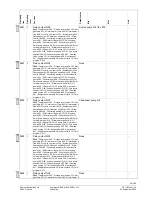
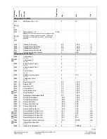
5990 I
Function input EX6
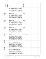
None ¦ Electrical utility lock E6 ¦ Low-tariff E5 ¦
Compressor 2 overload E12 ¦ Source overload E14 ¦
Pressure switch source E26 ¦ Flow switch source E15 ¦
Flow switch consumers E24 ¦ Manual defrost E17 ¦
Common fault HP E20 ¦ Fault soft starter E25 E25 ¦ Low-
pressure switch E9 ¦ High-pressure switch E10 ¦
Compressor 1 overload E11 ¦ Error/alarm message
Overload compressor 1
E11
-
5990 I
Function input EX6
None ¦ Electrical utility lock E6 ¦ Low-tariff E5 ¦
Compressor 2 overload E12 ¦ Source overload E14 ¦
Pressure switch source E26 ¦ Flow switch source E15 ¦
Flow switch consumers E24 ¦ Manual defrost E17 ¦
Common fault HP E20 ¦ Fault soft starter E25
Flow switch consumers
-
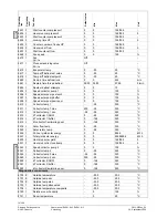
5992 I
Function input EX7
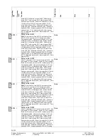
None ¦ Electrical utility lock E6 ¦ Low-tariff E5 ¦
Compressor 2 overload E12 ¦ Source overload E14 ¦
Pressure switch source E26 ¦ Flow switch source E15 ¦
Flow switch consumers E24 ¦ Manual defrost E17 ¦
Common fault HP E20 ¦ Fault soft starter E25 E25 ¦ Low-
pressure switch E9 ¦ High-pressure switch E10 ¦
Compressor 1 overload E11 ¦ Error/alarm message
None
-
5992 I
Function input EX7
None ¦ Electrical utility lock E6 ¦ Low-tariff E5 ¦
Compressor 2 overload E12 ¦ Source overload E14 ¦
Pressure switch source E26 ¦ Flow switch source E15 ¦
Flow switch consumers E24 ¦ Manual defrost E17 ¦
Common fault HP E20 ¦ Fault soft starter E25
None
-
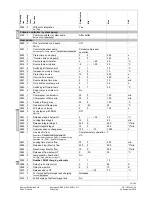
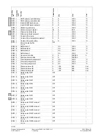
6014 I
Function mixing group 1
None ¦ Heating circ 1 ¦ Cooling circuit 1 ¦ Heating
circ/cooling circ 1 ¦ Prim contr/system pump ¦ DHW
primary controller ¦ Instantaneous DHW heater
Heating circuit 1
-
6020 I
Function extension module 1
None ¦ Multifunctional ¦ Cooling circuit 1 ¦ Heating circuit 2
¦ Solar DHW ¦ Prim contr/system pump ¦ DHW primary
controller ¦ Instantaneous DHW heater
None
-
6020 I
Function extension module 1
None ¦ Multifunctional ¦ Cooling circuit 1 ¦ Heating circuit 2
¦ Solar DHW ¦ Prim contr/system pump ¦ DHW primary
controller ¦ Instantaneous DHW heater
None
-
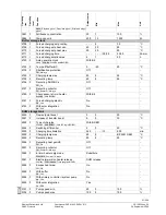
6021 I
Function extension module 2
None ¦ Multifunctional ¦ Cooling circuit 1 ¦ Heating circuit 2
¦ Solar DHW ¦ Prim contr/system pump ¦ DHW primary
controller ¦ Instantaneous DHW heater
None
-
6021 I
Function extension module 2
None ¦ Multifunctional ¦ Cooling circuit 1 ¦ Heating circuit 2
¦ Solar DHW ¦ Prim contr/system pump ¦ DHW primary
controller ¦ Instantaneous DHW heater
None
-
6030 I
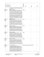
Relay output QX21
None ¦ Compressor 2 K2 ¦ Process revers valve Y22 ¦ Hot-
gas temp K31 ¦ El imm heater 1 flow K25 ¦ El imm heater 2
flow K26 ¦ Div valve cool source Y28 ¦ System pump Q14 ¦
Cascade pump Q25 ¦ Heat gen shutoff valve Y4 ¦ El imm
heater DHW K6 ¦ Circulating pump Q4 ¦ St tank transfer
None
-
4)
6)
4)
6)
6)
4)
6)
4)
6)
4)
6)
65/258
Siemens Switzerland Ltd
User manual RVS61.843, RVS41.813
CE1U2355en_02
HVAC Products
5 Handling
28. September 2009


