background image

CONFIGURATION 

_________________________________________________________________________________________________________ 

2-1 

SIG-QG-17-05                                                                                                                                                             DECEMBER 2017 
Version No.: A 


SECTION 2 - CONFIGURATION 


2.0 

CONFIGURATION 

The GCP Display module default settings will normally suffice for the majority of GCP 
installations. This section will show some of the initial display programming options to enable 
the user to customize the display serial and Ethernet ports. 
 

2.1 

DISPLAY MODULE MAIN SCREENS 

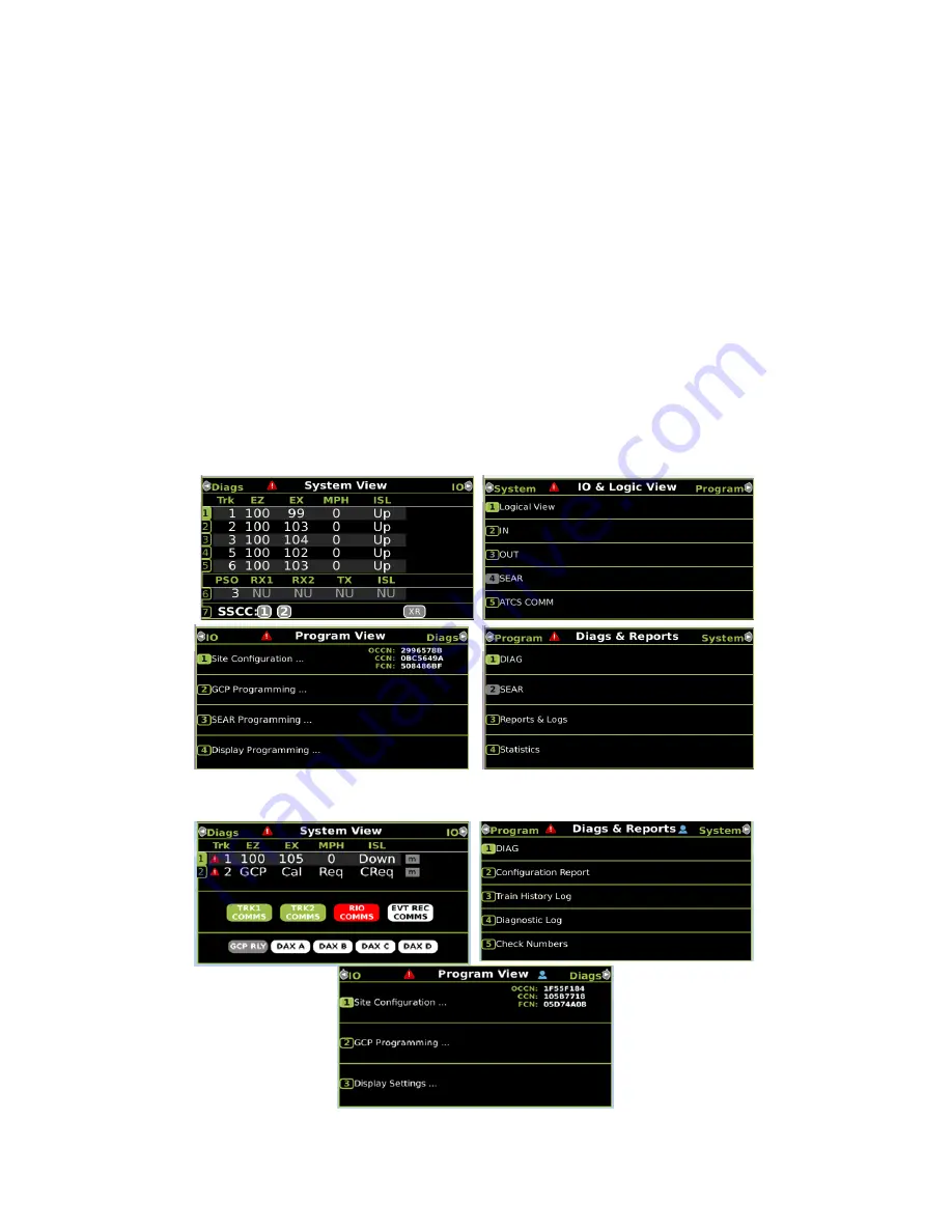
The display module main screens serve as the starting point for setup and operation of the GCP 
system.  The main screens for the GCP4000 and GCP5000 are shown in Figure  2-1  and the 
main screens for the  are shown in Figure 2-2.  


Figure 2-1   GCP4000 and GCP5000 Main Screens 


Figure 2-2    Main Screens 

Summary of Contents for A80485-1

Page 1: ...1 GCP DISPLAY MODULE CONFIGURATION AND OPERATION DECEMBER 2017 DOCUMENT NO SIG QG 17 05 VERSION A Siemens Industry Inc Rail Automation 700 East Waterfront Drive Munhall PA 15120 USA 1 800 793 SAFE Copyright 2017 Siemens Industry Inc All rights reserved ...

Page 2: ...current Terms and Conditions of Sale document Warranty adjustments will not be allowed for products or components which have been subjected to abuse alteration improper handling or installation or which have not been operated in accordance with Seller s instructions Alteration or removal of any serial number or identification mark voids the warranty SALES AND SERVICE LOCATIONS Technical assistance...

Page 3: ...iii SIG QG 17 05 DECEMBER 2017 Version No A DOCUMENT HISTORY Version Release Date Sections Changed Details of Change A DEC 2017 Initial Release ...

Page 4: ...1 4 SECTION 2 CONFIGURATION 1 1 2 0 CONFIGURATION 2 1 2 1 DISPLAY MODULE MAIN SCREENS 2 1 2 2 KEYPAD NAVIGATION CLUSTER 2 2 2 2 1 Keypad and Navigation Cluster Operation 2 2 2 3 SERIAL PORT 2 3 2 3 1 Configuring the Serial Port 2 3 2 4 ETHERNET PORTS 2 4 2 4 1 Ethernet Port Configuration 2 4 2 4 1 1 Server Mode 2 5 2 4 1 2 Client Mode 2 5 2 4 1 3 Disabled Mode 2 5 2 4 1 4 Laptop Ethernet Port Setu...

Page 5: ...ain Screens 2 1 Figure 2 2 GCP3000 Main Screens 2 1 Figure 2 3 Keypad and Navigation Cluster Keys 2 2 Figure 2 4 Keypad Operation 2 2 Figure 2 5 Navigation Key Cluster 2 2 Figure 3 1 Display Module to Laptop Connection 3 1 Figure 3 2 Inserting a USB Drive 3 3 Figure 3 3 USB Detected Screen 3 3 Figure 3 4 USB Menu Screens GCP4000 and GCP5000 3 4 Figure 3 5 USB Menu Screens GCP3000 3 4 Figure 3 6 Di...

Page 6: ...ESULT IN DEATH OR SERIOUS INJURY WARNINGS ALWAYS TAKE PRECEDENCE OVER NOTES CAUTIONS AND ALL OTHER INFORMATION CAUTION REFERS TO PROPER PROCEDURES OR PRACTICES WHICH IF NOT STRICTLY OBSERVED COULD RESULT IN A POTENTIALLY HAZARDOUS SITUATION AND OR POSSIBLE DAMAGE TO EQUIPMENT CAUTIONS TAKE PRECEDENCE OVER NOTES AND ALL OTHER INFORMATION EXCEPT WARNINGS NOTE Generally used to highlight certain info...

Page 7: ...ge of the circuit board but avoid touching circuit traces or components Handle circuit boards by the edges only Never physically touch circuit board or connector contact fingers or allow these fingers to come in contact with an insulator e g plastic rubber etc When not in use place circuit boards in approved static shielding bags contact fingers first Remove circuit boards from static shielding ba...

Page 8: ...GPS Global Positioning System IP Internet Protocol ISO Model Layer 3 network protocol that performs proper routing of packets LAN Local Area Network A limited network where the data transfer medium is generally wires or cable LED Light Emitting Diode A solid state indicator Module Physical package including PCBs and input output terminals for connecting to external devices and equipment RJ 45 Indu...

Page 9: ...laptop external network or Ethernet powered devices 1 1 GCP DISPLAY MODULE The Siemens A80485 1 Display Module is the next generation display module replacing the A80407 Display Module offering enhanced features and improved speed and responsiveness A restructured menu reduces programming and maintenance time in the field The addition of two Ethernet ports offers connectivity to a network or Ether...

Page 10: ...gure 1 2 and described in Table 1 1 Figure 1 2 A80485 GCP Display Module Controls Indicators and Display M9 1 Symbol 2 ABC 3 DEF 4 GHI 5 JKL 6 MNO 7 PQRS 8 TUV 9 WXYZ HELP 0 Space BACK ENTER USB LAPTOP DIAG CPU SEAR TX RX POWER TX RX DISPLAY Module A80485 2 COM TX RX ECHELON ETHERNET 2 ETHERNET 1 ETH PWR ESSR Powered Ethernet Port Keypad Navigation Keys USB Port Ethernet Port Unpowered Laptop Ethe...

Page 11: ...LED Green RX LED Yellow Echelon LAN Echelon LAN data indicators TX LED Green RX LED Yellow Ethernet 1 powered 1 Ethernet Power indicator LED Green Ethernet 1 data indicators embedded in connector Data TX LED Green RX LED Yellow Ethernet 21 Ethernet 2 data indicators embedded in connector TX LED Green RX LED Yellow CONNECTORS Ethernet 11 RJ 45 powered connector See note Ethernet 21 RJ 45 connector ...

Page 12: ...it This quick start guide is a supplemental document to be used in concert with the product manuals listed in Table 1 2 Table 1 2 Resource Documents DOCUMENT NUMBER TITLE SIG 00 17 03 GCP 3000 Installation Instruction SIG 00 17 04 GCP 3000 Application Guidelines SIG 00 08 06 GCP 4000 Application Guidelines SIG 00 08 10 GCP 4000 Field Manual SIG 00 10 05 GCE 4000 Application Guidelines SIG 00 12 68...

Page 13: ...installations This section will show some of the initial display programming options to enable the user to customize the display serial and Ethernet ports 2 1 DISPLAY MODULE MAIN SCREENS The display module main screens serve as the starting point for setup and operation of the GCP system The main screens for the GCP4000 and GCP5000 are shown in Figure 2 1 and the main screens for the GCP3000 are s...

Page 14: ... Cluster Operation The Display module keypad allows the user to select menus or enter data Press the desired key multiple times to select a letter number or symbol Figure 2 4 lists the alpha numeric sequence of each key The HELP key brings up a dialog box with instructions or information in some of the menus The BACK key returns to one of the four main screens Figure 2 4 Keypad Operation The Navig...

Page 15: ...for diagnostic functions and transferring software updates to other modules in the GCP case The serial port default settings are used for transferring software and therefore no serial port configuration is necessary 2 3 1 Configuring the Serial Port Should the user desire to change serial port settings use the following procedure 1 Navigate to the Program View screen using the left right navigatio...

Page 16: ...r these ports are Laptop Port Server Client Disabled Ethernet 1 and 2 Ports Disabled Client Denotes default setting NOTE The Ethernet 1 powered connector is designed specifically for Siemens Ethernet Spread Spectrum Radios and may not power other Power Over Ethernet POE devices 2 4 1 Ethernet Port Configuration The Laptop Ethernet port has three modes Server Client and Disabled The Ethernet 1 and ...

Page 17: ... Mode The Client mode is available on all three Ethernet ports In the Client mode the Display Ethernet port will be assigned an IP address from the external network server 2 4 1 3 Disabled Mode The Disabled mode shuts off the Ethernet port Ethernet ports 1 and 2 default setting is the disabled mode these ports may be configured as clients for use on a network and or external Ethernet devices 2 4 1...

Page 18: ...figure the port to either a client mode or to disable the port press the ENTER key 4 From the DHCP Configuration screen select the desired mode using the navigation keys and press the ENTER key NOTE For Laptop operation it is recommended to use the Server mode and setting the laptop DHCP to Client 5 In the Server mode the IP Address and Network Mask are pre assigned from the factory and cannot be ...

Page 19: ...d or use the navigation keys and select Display Programming then press the ENTER key 2 From the Display screen select Ethernet Ports press 2 on the keypad or use the navigation keys and select Ethernet Ports and press the ENTER key 3 From the Ethernet Ports screen select either Port 1 or Port 2 press 2 or 3 on the keypad or use the navigation keys and select Port 1 or Port 2 then press the ENTER k...

Page 20: ...their network operations Refer to the GCP manual for further instructions on setting DNS servers 2 4 1 7 Ethernet Port Status The status of the Display module Ethernet ports can be viewed by selecting the Status tab on the Laptop Ethernet 1 or Ethernet 2 screen The status of all three ports can be viewed regardless of which Ethernet port screen is selected 2 4 2 Display Options Settings The Displa...

Page 21: ... configured 3 1 1 Display Module to Laptop Connection To connect a laptop to the Display module plug an RJ 45 to RJ 45 Ethernet cable from the Laptop port on the front panel of the Display module to any Ethernet port on the laptop The Display module DHCP should be set up as a server and the laptop DHCP set up as a client Using a web browser on the laptop enter the Display IP address 192 168 255 81...

Page 22: ...ure be created on the USB Drive prior to use on the Display USB port The GCP system looks for specific file folders to locate upload or download files The file structure is as follows SIEMENS o DOT SITE NAME GCP4000 CONFIGURATIONS PAC FILES REPORTS YYYY MON GCP4000 oAPPLICATIONS MCF PAC oEXECUTIVES MEF TGZ BIN PAC files or MCFs to be uploaded should be placed under the GCP4000 Applications Executi...

Page 23: ...ure 3 2 Inserting a USB Drive 3 2 3 USB Detection When the USB drive is inserted into the USB port the Display module will display a screen advising the USB drive has been detected Press the ENTER key on the navigation key cluster to bring up the USB Menu or press the BACK key on the keypad to exit Figure 3 3 USB Detected Screen M9 1 Symbol 2 ABC 3 DEF 4 GHI 5 JKL 6 MNO 7 PQRS 8 TUV 9 WXYZ HELP 0 ...

Page 24: ...le Executive software update The other USB menu sub menus provide for downloading of configuration reports display event logs GCP logs train history and uploading or downloading configuration files The GCP s current configuration information can be downloaded to the USB drive A new configuration can also be uploaded to the GCP via the USB drive Refer to the appropriate manual for your GCP unit for...

Page 25: ... port of the GCP module receiving the software update as shown in Figure 3 6 Refer to the appropriate manual for your GCP for further details on uploading software to GCP modules Figure 3 6 Display Module to GCP Module Serial Cable Connection 3 4 DISPLAY MODULE POWERED ETHERNET PORT The Display module Ethernet 1 port is a powered port for external Ethernet devices that derive their power from an E...

Page 26: ...Ethernet 1 port Power Over Ethernet device connection using the Siemens Ethernet Spread Spectrum Radio is shown in Figure 3 7 Connection from the GCP Display to the Ethernet powered device is usually connected using an Ethernet cable that is provided with the Ethernet device Refer to the Ethernet device instructions for further information Figure 3 7 Display Module to Ethernet Power Over Ethernet ...

Page 27: ...ent mode see Section 2 4 1 5 for details or for the Laptop port see Section 2 4 1 4 the external network will assign the Display module an IP address and establish communications WARNING DO NOT CONNECT A NETWORK TO THE LAPTOP ETHERNET PORT IF THE PORT HAS BEEN CONFIGURED AS A SERVER THIS WILL CAUSE DISRUPTION TO THE NETWORK IF A NETWORK IS TO BE CONNECTED TO THE LAPTOP PORT CONFIGURE THE LAPTOP PO...

Page 28: ...OPERATION _________________________________________________________________________________________________________ 3 8 SIG QG 17 05 DECEMBER 2017 Version No A This Page Intentionally Left Blank ...

Page 29: ...NOTES ...

Page 30: ...NOTES ...

Page 31: ...NOTES ...

Page 32: ...emens Industry Inc Rail Automation 2400 Nelson Miller Parkway Louisville Kentucky 40223 502 618 8800 Siemens Industry Inc Rail Automation 700 East Waterfront Drive Munhall Pennsylvania 15120 412 461 2501 ...

Reviews: