

129-287
Operating Instructions
Rev. 1, October, 1999
Page 6 of 8
Siemens Industry, Inc.
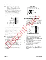
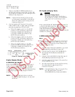
3.
Depress the SELECT MODE pushbutton to
activate the floating control mode. A green LED
should light and indicate that the floating control
mode is active (
Figure 1
3).
NOTE:
The level of the floating control output
control signal is equivalent to the level of
the 24 Vac power signal coming into the
Commissioning Tool.
4.
Use the toggle switch (
Figure 13
) to select
CCW, STOP, or CW. A green LED should light
and indicate selection of CCW or CW.
•
When the toggle switch is in the STOP
position, 0 Vac (nominal) is output from
Terminals 2 (COM) and 3 (CCW), and
Terminals 2 (COM) and 4 (CW) of the
OUTPUTS terminal block.
•
When the toggle switch is in the CCW
position, 24 Vac (nominal) is output from
Terminals 2 (COM) and 3 (CCW) of the
OUTPUTS terminal block.
•
When the toggle switch is in the CW
position, 24 Vac (nominal) is output from
Terminals 2 (COM) and 4 (CW) of the
OUTPUTS terminal block.
Figure 13. Floating Control Mode.
Digital Display Modes
OUTPUT Display Mode
When the OUTPUT/DC FEEDBACK toggle switch
(
Figure 11
) is in the OUTPUT position, the digital
display reads the level of the voltage or current
control signal that is output from the Commissioning
Tool during the proportional voltage and current
modes.
NOTE:
During the floating control or resistive
modes, the digital display is not used and
reads zero.
DC Feedback Display Mode
CAUTION
:
Equipment Damage Hazard.
Do not apply signals greater than 30 Vdc or
any AC signals to Terminal 7 (DC FEEDBACK)
or damage to the Commissioning Tool can
result.
When the OUTPUT/DC FEEDBACK toggle switch is
in the DC FEEDBACK position, the Commissioning
Tool functions as a voltmeter. The digital display
shows the level of the DC voltage signal that is
applied between Terminals 7 (DC FEEDBACK) and 8
(COM) of the INPUTS terminal block.
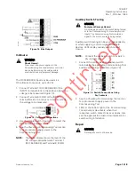
Additional Testing Features
Bias
The +5 Vdc Bias output cab be used in conjunction
with the DC FEEDBACK and COM inputs to verify
proper operation of floating control actuators with
feedback potentiometers.
1.
Connect output Terminal 6 (BIAS) to one end of
the feedback potentiometer (
Figure 14
).
2.
Connect input Terminal 7 (DC FEEDBACK) to
the wiper of the feedback potentiometer
(
Figure 14
).
3.
Connect Terminal 8 (COM) to the other end of
the feedback potentiometer (Figure
14
).
4.
Use the toggle switch (
Figure 11
) to select the
DC FEEDBACK display.
5.
See the
Powering Commissioning Tool
section
for a procedure to apply power to the
Commissioning Tool.
NOTE:
The digital display shows the level of the
DC voltage between Terminal 7
(DC FEEDBACK) and Terminal 8 (COM).


