background image

Ring Topology

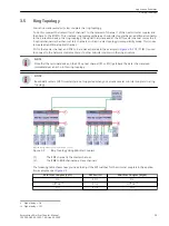
You can cascade several mini star couplers in a ring topology.
To do this, connect the transmitter of channel 1 to the receiver of channel 1 of the next mini star coupler and
then back to the PC/RTU. This creates a ring topology where each mini star coupler has an additional connector
to the protection device. In a ring topology, the signal that is received at the FO1 master channel comes to all
5 optical channels rather than just to 4 channels, such as in a star topology in compatibility mode. This is how
to create an additional optical channel.
FO1 is the master channel, and FO2 to 5 are slave channels in the example in 

Figure 3-5

. FO1 (T1/R1) is used

to connect to the network control center or to other mini star couplers in the ring structure.

i

i

NOTE

Note that the terminal device on the FO1 optical channel (PC or RTU) gets back the data it has received
immediately as an echo in this ring topology.

i

i

NOTE

Redundant centers (2 RTU masters) are not supported when you cascade several mini star couplers in a ring
topology.

[dw_example_ring-topology_with_mini-star-coupler, 1, en_US]

Figure 3-5

Ring Topology Using Mini Star Couplers

(1)

The FO1 channel is the master channel.

(2)

The FO2 to FO5 channels are slave channels.

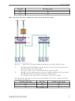
The following table shows how you need to adjust the DIP switches for the mini star couplers in the applica-
tion example as per 

Figure 3-5

.

Mini Star Coupler (Left)

DIP Switch

Mini Star Coupler (Right)

On

S 1/1

On

Off

9

 On

10

S 1/2

Off

9

 On

10

Off

S 1/3

Off

3.5

9

Signal delay = On

10

Signal delay = Off

Application Examples

3.5 Ring Topology

Accessories, Mini Star Coupler, Manual

29

C53000-G9050-C595-1, Edition 05.2020

Summary of Contents for 7XV5450-0BA00/BB

Page 1: ...ni Sternkoppler 7XV5450 0BA00 ab Version DD Handbuch C53000 G9050 C595 1 Vorwort Inhaltsverzeichnis Einführung 1 Aufbau des Gerätes 2 Anwendungsbeispiele 3 Montage und Inbetriebnahme 4 Technische Daten 5 Anhang A ...

Page 2: ...d nur dann verbindlich wenn sie bei Vertragsschluss ausdrücklich vereinbart werden Dokumentversion C53000 G9050 C595 1 02 Ausgabestand 05 2020 Version des beschriebenen Produkts ab Version DD Copyright Copyright Siemens AG 2020 Alle Rechte vorbehalten Weitergabe sowie Vervielfältigung Verbreitung und Bear beitung dieses Dokuments Verwertung und Mitteilung des Inhaltes sind unzulässig soweit nicht ...

Page 3: ...änkung der Nutzung von gefährlichen Substanzen in elektrischen und elektronischen Geräten RoHS Richtlinie 2011 65 EU sowie elektrische Betriebsmittel zur Verwendung inner halb bestimmter Spannungsgrenzen Niederspannungsrichtlinie 2014 35 EU Diese Konformität ist das Ergebnis einer Bewertung die durch die Siemens AG gemäß den Richtlinien in Übereinstimmung mit den Fachgrundnormen EN 61000 6 2 und E...

Page 4: ...oder schwere Verletzungen zu vermeiden WARNUNG WARNUNG bedeutet dass Tod oder schwere Verletzungen eintreten können wenn die angegebenen Maßnahmen nicht getroffen werden Beachten Sie alle Hinweise um Tod oder schwere Verletzungen zu vermeiden VORSICHT VORSICHT bedeutet dass mittelschwere oder leichte Verletzungen eintreten können wenn die angege benen Maßnahmen nicht getroffen werden Beachten Sie ...

Page 5: ...ufig bestimmte Teile unter gefährlicher Spannung Wenn nicht fachgerecht gehandelt wird können Tod schwere Verletzungen oder Sachschäden auftreten Das Betriebsmittel muss vor Anschluss von Verbindungen am Erdungsanschluss geerdet werden Gefährliche Spannungen können in allen mit der Spannungsversorgung verbundenen Schaltungsteilen anstehen Auch nach Abtrennen der Spannungsversorgung können gefährli...

Page 6: ...mbol Beschreibung 9 Richtlinie 2002 96 EC über Elektro und Elektronikgeräte 10 Richtlinie für die eurasische Wirtschaftsunion Vorwort 6 Zubehör Mini Sternkoppler Handbuch C53000 G9050 C595 1 Ausgabe 05 2020 ...

Page 7: ...modus 25 3 4 Sterntopologie mit Master Redundanz erweiterter Modus 26 3 5 Ringtopologie 29 3 6 Zeitsynchronisation von SIPROTEC Geräten 30 4 Montage und Inbetriebnahme 33 4 1 Montage 34 4 2 Anschluss 36 4 2 1 Hilfsspannung X2 36 4 2 2 Störmeldeanschluss X7 36 4 2 3 LWL Anschlüsse Tx Rx 36 4 3 Inbetriebnahme 37 4 4 Wartung 38 4 5 Aus und Wiedereinschalten des Gerätes 39 4 6 Umwelthinweise 40 5 Tech...

Page 8: ...A Anhang 47 A 1 Bestelldaten und Zubehör 48 A 2 Maße 49 Inhaltsverzeichnis 8 Zubehör Mini Sternkoppler Handbuch C53000 G9050 C595 1 Ausgabe 05 2020 ...

Page 9: ...Einführung 1 1 Anwendungsbereich 10 1 Zubehör Mini Sternkoppler Handbuch 9 C53000 G9050 C595 1 Ausgabe 05 2020 ...

Page 10: ...n mit erhöhten Anforderungen an die Sicherheit und Genauigkeit der Datenübertragung Erhöhte Sicherheitsanforderungen gibt es z B bei der Verbindung von SIPROTEC Geräten mit einem DIGSI PC SCADA RTU oder bei der Zeitsynchronisation mit einem zentralen Zeitsignalgeber Die Betriebsmodi sind mit DIP Schaltern von außen einstellbar Der Mini Sternkoppler besitzt eine RS232 Schnittstelle und 5 optische A...

Page 11: ...Aufbau des Gerätes 2 1 Geräteübersicht 12 2 2 Geräteanschlüsse 13 2 Zubehör Mini Sternkoppler Handbuch 11 C53000 G9050 C595 1 Ausgabe 05 2020 ...

Page 12: ... DIN EN 50022 Die Hilfsspannung wird über 2 Klemmen angeschlossen Der große Hilfsspannungsbereich von DC 24 V bis 250 V und AC 60 V bis 230 V erlaubt den Anschluss an alle gängigen Stationsbatterien oder Wechselspannungsnetze Die RS232 Schnittstelle wird über die 9 polige D Sub Buchse X1 angeschlossen Die LWL Kanäle werden über ST Anschlüsse angeschlossen Über den potentialfreien Meldekontakt X7 K...

Page 13: ...g sc_front_starcoupler 1 _ Bild 2 1 Vorderansicht sc_bottom_starcoupler 1 _ Bild 2 2 Ansicht von unten 2 2 2 2 1 Aufbau des Gerätes 2 2 Geräteanschlüsse Zubehör Mini Sternkoppler Handbuch 13 C53000 G9050 C595 1 Ausgabe 05 2020 ...

Page 14: ...h Sie müssen den Sender T an den Empfänger R der Gegenseite anschließen und umgekehrt DIP Schalter S1 Der DIP Schalter S1 befindet sich auf der Unterseite des Gerätes und hat 8 von außen bedienbare DIP Schalter siehe Bild 2 2 Über die DIP Schalter stellen Sie z B den Betriebsmodus des Mini Sternkopplers ein Weitere Informationen siehe 2 2 2 1 DIP Schalter S1 Belegung der Anschlüsse und Schalterste...

Page 15: ...k arbeiten ist ein Schalter integriert Mit dem Schalter können Sie jeden Kanal auf negative Logik Licht im Ruhezustand umschalten Der optische Eingang und der optische Ausgang dieser Schnittstellen werden hierbei gleichzeitig invertiert Damit bei negativer Logik der Mini Sternkoppler nicht blockiert wird benötigt jeder Empfangskanal im Ruhezustand Licht Tabelle 2 1 zeigt die möglichen Standardeins...

Page 16: ...er Anschluss On On Kaskadierung Ringtopologie RS232 Off Dieser Modus eignet sich z B für die Zeitsynchronisation von SIPROTEC Geräten siehe Bild 3 6 Hinweis Auch wenn Sie ein DIGSI Kabel anschließen bleibt bei dieser DIP Schalterstellung die Schnittstelle RS232 Off Signalverzögerung Off Kürzere Signallaufzeit als in 7XV5450 0BA00 CC und BB Wenn die Ringtopologie aktiviert ist werden die Signale vo...

Page 17: ...r Logik der Mini Sternkoppler nicht blockiert wird benötigt jeder Empfangskanal im Ruhezustand Licht Weitere Informationen siehe 3 2 Betriebsmodi und Datentransfer Tabelle 2 2 DIP Schalter S1 im erweiterten Modus Mini Sternkoppler 7XV5450 0BA00 DD Schalter Stellung Bedeutung S1 1 S1 2 S1 1 S1 2 Off Off Kaskadierung Sterntopologie RS232 Off Hinweis Auch wenn Sie ein DIGSI Kabel an die Buchse X1 ans...

Page 18: ...ilt jetzt die Daten auf die LWL Kanäle oder empfängt Daten von den LWL Kanälen Dadurch verhindern Sie eine Datenkollision durch gleichzeitigen Lokal und Fernzugriff Im erweiterten Modus Sterntopologie mit Master Redundanz gibt es weitere Einstellmöglichkeiten für die Funktionalität der RS232 Schnittstelle Tabelle 2 1 und Tabelle 2 2 zeigen in welchen Modi die RS232 Schnittstelle benutzt wird RS232...

Page 19: ... können Sie bei Siemens mit den Bestellnummern 6XV8100 oder 6XV8200 bestellen Verbinden Sie die LWL Kabel über die ST Anschlüsse mit den entsprechenden LWL Elementen i i HINWEIS Achten Sie bei der Verlegung von LWL Kabeln auf den vorgeschriebenen Biegeradius i i HINWEIS Schrauben Sie die D Sub Steckverbinder nach dem Anschließen am Gerät fest 2 2 2 3 Aufbau des Gerätes 2 2 Geräteanschlüsse Zubehör...

Page 20: ...20 Zubehör Mini Sternkoppler Handbuch C53000 G9050 C595 1 Ausgabe 05 2020 ...

Page 21: ...entransfer 23 3 3 Sterntopologie Kompatibilitätsmodus 25 3 4 Sterntopologie mit Master Redundanz erweiterter Modus 26 3 5 Ringtopologie 29 3 6 Zeitsynchronisation von SIPROTEC Geräten 30 3 Zubehör Mini Sternkoppler Handbuch 21 C53000 G9050 C595 1 Ausgabe 05 2020 ...

Page 22: ... Konfi gurationen sind möglich Sterntopologie Sterntopologie mit Master Redundanz Ringtopologie i i HINWEIS Der Mini Sternkoppler hat eine RS232 Buchse Wenn Sie einen PC RTU über das Kabel 7XV5100 4 an die RS232 Schnittstelle anschließen und das Gerät in Sterntopologie im Kompatibilitätsmodus konfiguriert ist wird der optische Eingang LWL 1 automatisch getrennt Dadurch verhindern Sie eine Datenkol...

Page 23: ...iehe 3 3 Sterntopologie Kompatibilitätsmodus Kaskadierung Stern Ringtopologie RS232 On i i HINWEIS In den Betriebsmodi Sterntopologie RS232 On und Ringtopologie RS232 On ist der Datentransfer gleich Deshalb werden beide Modi im Modus Stern Ringtopologie RS232 On zusammengefasst Modus Datentransfer Kaskadierung Stern Ringtopologie RS232 On DIGSI Kabel gesteckt Empfangskanäle Sendekanäle RX RS232 R2...

Page 24: ...rntopologie mit Master Redundanz erweiterter Modus Bild 3 2 Externe Master Redundanz in einer Sterntopologie Modus Datentransfer Externe Master Redundanz in einer Sterntopologie Master 1 LWL Kanal 1 Empfangskanäle Sendekanäle R1 R2 RX RS232 Empfang R3 bis R5 TX RS232 Senden T2 bis T5 TX RS232 Senden T1 T3 bis T5 T1 T2 Master 2 LWL Kanal 2 Erweiterter Modus i i HINWEIS Die RS232 Schnittstelle ist e...

Page 25: ...geschlossen ist ist der Kanal LWL 1 und damit auch die Fernverbindung abgeschaltet Die Kanäle LWL 1 oder RS232 sind Master Kanäle Die Kanäle LWL 2 bis LWL 5 sind Slave Kanäle für den Anschluss der Schutzgeräte i i HINWEIS An den Kanal LWL 1 T1 R1 dürfen Sie keine Schutzgeräte Slaves anschließen Der Kanal LWL 1 T1 R1 dient nur der Verbindung mit der Netzleitstelle dw_example_star topology_with_mini...

Page 26: ...Stellen Sie über ein Protokoll zwischen Master 1 und Master 2 sicher dass nicht beide Master gleichzeitig senden Dadurch verhindern Sie eine Datenkollision Master Kanäle RS232 und LWL 2 dw_example_master startopology rs232only 1 de_DE Bild 3 2 Beispiel 1 Sterntopologie mit Mini Sternkopplern und Master Redundanz erweiterter Modus 1 Die RS232 Schnittstelle und der Kanal LWL 2 sind Master Kanäle 2 D...

Page 27: ...n arbeitet im erweiterten Modus 2 Der Kanal LWL 1 ist hier ein zusätzlicher Slave Kanal LWL 3 LWL 4 und LWL 5 sind ebenfalls Slave Kanäle Der Kanal LWL 5 wird für die Kaskadierung weiterer Mini Sternkoppler Geräte benutzt Die kaskadierten Mini Sternkoppler arbeiten in der Sterntopologie im Kompatibilitäts Modus Die folgende Tabelle zeigt wie Sie die DIP Schalter der Mini Sternkoppler im Anwendungs...

Page 28: ...e 2 Die Kanäle LWL 3 LWL 4 LWL 5 und die RS232 Schnittstelle sind Slave Kanäle Die folgende Tabelle zeigt wie Sie die DIP Schalter der Mini Sternkoppler im Anwendungsbeispiel nach Bild 3 4 einstellen müssen DIP Schalter Mini Sternkoppler S 1 1 On S 1 2 On S 1 3 On Anwendungsbeispiele 3 4 Sterntopologie mit Master Redundanz erweiterter Modus 28 Zubehör Mini Sternkoppler Handbuch C53000 G9050 C595 1...

Page 29: ...en Mini Sternkopplern in der Ringstruktur benutzt i i HINWEIS Beachten Sie dass in der Ringtopologie das Endgerät am optischen Kanal LWL1 PC oder RTU seine gesen deten Daten unmittelbar als Echo zurückbekommt i i HINWEIS Wenn Sie mehrere Mini Sternkoppler in einer Ringtopologie kaskadieren werden redundante Zentralen 2 RTU Master nicht unterstützt dw_example_ring topology_with_mini star coupler 1 ...

Page 30: ...piele für die Benutzung des Mini Sternkopplers bei der Zeitsynchronisation von SIPROTEC Geräten finden Sie im Handbuch des Sync Transceivers 7XV5654 0BA00 Bestellnummer C53000 G9050 C168 1 dw_timesynchronisation SIP4 devices 1 de_DE Bild 3 6 Zeitsynchronisation von mehr als 12 SIPROTEC Geräten 3 6 Anwendungsbeispiele 3 6 Zeitsynchronisation von SIPROTEC Geräten 30 Zubehör Mini Sternkoppler Handbuc...

Page 31: ...piel nach Bild 3 6 einstellen müssen Mini Sternkoppler links DIP Schalter Für weitere kaskadierte Mini Stern koppler On S 1 1 On On S 1 2 On Off S 1 3 Off Anwendungsbeispiele 3 6 Zeitsynchronisation von SIPROTEC Geräten Zubehör Mini Sternkoppler Handbuch 31 C53000 G9050 C595 1 Ausgabe 05 2020 ...

Page 32: ...32 Zubehör Mini Sternkoppler Handbuch C53000 G9050 C595 1 Ausgabe 05 2020 ...

Page 33: ...iebnahme 4 1 Montage 34 4 2 Anschluss 36 4 3 Inbetriebnahme 37 4 4 Wartung 38 4 5 Aus und Wiedereinschalten des Gerätes 39 4 6 Umwelthinweise 40 4 Zubehör Mini Sternkoppler Handbuch 33 C53000 G9050 C595 1 Ausgabe 05 2020 ...

Page 34: ...022 vorge sehen Hängen Sie das Gerät zur Montage von oben auf die Hutschiene und drücken Sie es an bis das Gerät aufgeschnappt Zum Lösen von der Hutschiene ziehen Sie den Hutschienenschieber mit einem Schraubendreher o ä nach unten dann nehmen Sie das Gerät entgegen der Aufschnappbewegung von der Hutschiene Die Datenleitungen für die elektrischen RS232 Schnittstellen müssen in geschirmten und geer...

Page 35: ...aturbereichs kann zu Fehlfunktionen Ausfall und zur Zerstörung des Gerätes führen Die angegebenen Funktionstemperaturbereiche müssen eingehalten werden Montage und Inbetriebnahme 4 1 Montage Zubehör Mini Sternkoppler Handbuch 35 C53000 G9050 C595 1 Ausgabe 05 2020 ...

Page 36: ... 5 mm2 Empfohlene Abisolierlänge 3 mm bis 5 mm bei Crimp Anschlüssen LWL Anschlüsse Tx Rx i i HINWEIS Verwenden Sie nur vorschriftsmäßig konfektionierte Lichtwellenleiter Bestellnummer 6XV8100 oder 6XV8200 Schrauben Sie die D Sub Steckverbinder nach dem Anschließen am Gerät fest Achten Sie bei der Verlegung von LWL Kabeln auf den vorgeschriebenen Biegeradius Achten Sie auf die Einhaltung des zuläs...

Page 37: ... Anschlüsse handfest Stecken und verschrauben Sie den RS232 Anschluss Verbinden Sie die Anschlüsse der Hilfsspannung mit der Anschlussklemme Uaux DC L L oder AC L1 N N und L Schalten Sie die Hilfsspannungsversorgung ein Nach dem Zuschalten der Hilfsspannungsversorgung leuchtet die grüne LED RUN und das Gerät ist betriebsbe reit 4 3 Montage und Inbetriebnahme 4 3 Inbetriebnahme Zubehör Mini Sternko...

Page 38: ...und fusselfreies Tuch Decken Sie die LWL Anschlüsse vor der Reinigung mit den dafür vorgesehenen Abdeckungen staubdicht ab i i HINWEIS Verwenden Sie zur Reinigung keine Flüssigkeiten 4 4 Montage und Inbetriebnahme 4 4 Wartung 38 Zubehör Mini Sternkoppler Handbuch C53000 G9050 C595 1 Ausgabe 05 2020 ...

Page 39: ...das Gerät für mindestens 3 5 s ausgeschaltet bleiben bevor Sie es wieder einschalten Wenn Sie das Gerät vor Ablauf der 3 5 s einschalten muss das Gerät für 5 Minuten ausgeschaltet bleiben Erst danach ist ein Wiedereinschalten zur Aktivierung des Gerätes möglich 4 5 Montage und Inbetriebnahme 4 5 Aus und Wiedereinschalten des Gerätes Zubehör Mini Sternkoppler Handbuch 39 C53000 G9050 C595 1 Ausgabe...

Page 40: ...en nicht mit normalem Hausmüll vermischt werden dürfen Ein Verstoß gegen die Richtlinie kann gemäß lokaler Gesetzgebung Bußgelder nach sich ziehen Durch die korrekte Entsorgung dieser Produkte helfen Sie wertvolle Ressourcen zu sparen und mögliche nega tive Folgen auf die menschliche Gesundheit und die Umwelt zu verringern i i HINWEIS Unsere Produkte und Batterien dürfen nicht als Hausmüll entsorg...

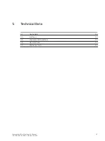
Page 41: ...e Daten 5 1 Gerätedaten 42 5 2 Schnittstellen 43 5 3 Umgebungsbedingungen 44 5 4 Elektrische Prüfungen 45 5 5 Mechanische Prüfungen 46 5 Zubehör Mini Sternkoppler Handbuch 41 C53000 G9050 C595 1 Ausgabe 05 2020 ...

Page 42: ... VA Netzausfallüberbrückung Mind 50 ms bei Nennlast Zustandsanzeige der Ausgangsspannung 1 grüne LED zur Anzeige des Betriebszustands Störmeldeanschluss Relais Relais MSR Relais 1 Öffner potentialfrei 2 polige Klemme Maximale Schaltspannung bei ohmscher Last AC 240 V Maximaler Schaltstrom 5 A Maximale Schaltleistung AC 2000 VA Zulässiger Strom für Kontakte 5 A Prüfspannung Ueff 3 51 kV Sicherungen...

Page 43: ...62 5 μm 125 μm Empfindlichkeit 30 dBm Optisches Budget 10 dB 3 dB Systemreserve Minimale Reichweite 1 5 km mit Glasfaser 3 5 m mit Kunststoff Faser 980 μm 1000 μm Minimale Baud Rate 0 Baud Maximale Baud Rate 115 200 Baud bei gleichzeitiger Benutzung der RS232 und der LWL Schnittstellen 1 MBd bei ausschließlicher Benutzung der LWL Schnittstellen Laufzeiten bei LWL Betrieb nicht für RS232 Mini Stern...

Page 44: ...gkeit Mittlere relative Luftfeuchte 75 Maximale relative Luftfeuchte 95 an 30 Tagen pro Jahr Kondensation im Betrieb Nicht zulässig Kondensation bei Transport und Lagerung Zulässig Maximale Höhe über dem Meeresspiegel 2000 m Verschmutzungsgrad 2 Schutzklasse gemäß IEC 60529 IP 20 Überspannungskategorie III 5 3 Technische Daten 5 3 Umgebungsbedingungen 44 Zubehör Mini Sternkoppler Handbuch C53000 G...

Page 45: ...rüfdauer 1 Minute VDE 0435 Teil 303 Klasse III 2 5 kV Längsspannung 1 kV Querspannung Entladung statischer Elektrizität IEC 60255 26 Klasse III EN 61000 4 2 Klasse III 6 kV Kontaktentladung 8 kV Luftentladung beide Polaritäten 150 pF Ri 330 Ω Bestrahlung mit HF Feld amplitudenmoduliert IEC 61000 4 3 10 V m 80 MHz bis 1000 MHz 80 AM 1 kHz Bestrahlung mit HF Feld pulsmoduliert IEC 61000 4 3 35 V m 9...

Page 46: ...hleunigung horizontale Achse 8 Hz bis 35 Hz 1 g Beschleunigung vertikale Achse Frequenzdurchlauf 1 Oktave min 1 Zyklus in 3 Achsen senkrecht zuei nander Schwing und Schockbeanspruchung bei Transport und Lagerung Schwingung Sinusförmig IEC 60068 2 6 IEC 60255 21 1 Klasse 2 5 Hz bis 8 Hz 7 5 mm Amplitude 8 Hz bis 150 Hz 2 g Beschleunigung Frequenzdurchlauf 1 Oktave min 20 Zyklen in 3 Achsen senkrech...

Page 47: ...Anhang A 1 Bestelldaten und Zubehör 48 A 2 Maße 49 A Zubehör Mini Sternkoppler Handbuch 47 C53000 G9050 C595 1 Ausgabe 05 2020 ...

Page 48: ... anten Bestell Nr DIGSI Kabel 1 2 3 4 5 6 7 8 9 10 11 12 PC 9 polige Buchse und Schutzgerät 7 X V 5 1 0 0 2 25 poliger Stecker Länge 3 m PC 9 polige Buchse und Schutzgerät 4 9 poliger Stecker Länge 3 m PC 25 polige Buchse und Schutzgerät 5 9 poliger Stecker Länge 3 m RS232 RS485 Konverter 25 poliger Stecker und Schutzgerät Einzeldraht Ringkabelschutz Länge 1 m 7 Steckeradapter 9 polige Buchse 25 p...

Page 49: ...Maße dw_dimensions_mini starcoupler_7XV5450_big 1 de_DE Bild A 1 Maße in mm A 2 Anhang A 2 Maße Zubehör Mini Sternkoppler Handbuch 49 C53000 G9050 C595 1 Ausgabe 05 2020 ...

Page 50: ...50 Zubehör Mini Sternkoppler Handbuch C53000 G9050 C595 1 Ausgabe 05 2020 ...

Page 51: ...ini Star Coupler 7XV5450 0BA00 Version DD and higher Manual C53000 G9050 C595 1 Preface Table of Contents Overview 1 Device Structure 2 Application Examples 3 Assembly and Commissioning 4 Technical Data 5 Appendix A ...

Page 52: ...re binding only when they are expressly agreed upon in the concluded contract Document version C53000 G9050 C595 1 02 Edition 05 2020 Version of the product described Version DD and higher Copyright Copyright Siemens 2020 All rights reserved The disclosure duplication distribution and editing of this document or utilization and communication of the content are not permitted unless authorized in wr...

Page 53: ... EMC Directive 2014 30 EU restriction on usage of hazardous substances in electrical and electronic equipment RoHS Directive 2011 65 EU and electrical equipment for use within specified voltage limits Low Voltage Directive 2014 35 EU This conformity has been proved by tests performed according to the Council Directive in accordance with the generic standards EN 61000 6 2 and EN 61000 6 4 for EMC d...

Page 54: ...avoid death or severe injuries CAUTION CAUTION means that medium severe or slight injuries can occur if the specified measures are not taken Comply with all instructions in order to avoid moderate or minor injuries NOTICE NOTICE means that property damage can result if the measures specified are not taken Comply with all instructions in order to avoid property damage i i NOTE Important information...

Page 55: ...uipment even after the supply voltage has been disconnected capacitors can still be charged Operation of equipment with exposed current transformer circuits is prohibited Before disconnecting the equipment ensure that the current transformer circuits are short circuited The limiting values stated in the document must not be exceeded This must also be considered during testing and commissioning Sel...

Page 56: ...6 Accessories Mini Star Coupler Manual C53000 G9050 C595 1 Edition 05 2020 ...

Page 57: ...25 3 4 Star Topology with Master Redundancy Extended Mode 26 3 5 Ring Topology 29 3 6 Time Synchronization for SIPROTEC Devices 30 4 Assembly and Commissioning 33 4 1 Montage 34 4 2 Connection 36 4 2 1 Auxiliary Voltage X2 36 4 2 2 Fault Signaling Connection X7 36 4 2 3 Fiber Optic Connections Tx Rx 36 4 3 Commissioning 37 4 4 Maintenance 38 4 5 Switching The Device Off and On Again 39 4 6 Environ...

Page 58: ...A Appendix 47 A 1 Ordering Information and Accessories 48 A 2 Dimensions 49 Table of Contents 8 Accessories Mini Star Coupler Manual C53000 G9050 C595 1 Edition 05 2020 ...

Page 59: ...Overview 1 1 Scope of Application 10 1 Accessories Mini Star Coupler Manual 9 C53000 G9050 C595 1 Edition 05 2020 ...

Page 60: ...tions with strict security and data transmission accuracy requirements The safety requirements are more stringent for example when connecting SIPROTEC devices to a DIGSI PC SCADA or RTU or when carrying out time synchronization with a centralized time signal generator The operating modes can be adjusted externally using DIP switches The mini star coupler has an RS232 interface and 5 optical connec...

Page 61: ...Device Structure 2 1 Device Overview 12 2 2 Device Connections 13 2 Accessories Mini Star Coupler Manual 11 C53000 G9050 C595 1 Edition 05 2020 ...

Page 62: ...iary voltage is connected via 2 terminals The large auxiliary voltage ranges of DC 24 V to 250 V and AC 60 V to 230 V allow connection to all common station batteries or alternating voltage networks The RS232 interface is connected using the 9 pin X1 D sub socket The fiber optic channels are connected using ST connectors Using the isolated signaling contact X7 terminal 1 2 a failure indication can...

Page 63: ...ement sc_front_starcoupler 1 _ Figure 2 1 Front View sc_bottom_starcoupler 1 _ Figure 2 2 Bottom View 2 2 2 2 1 Device Structure 2 2 Device Connections Accessories Mini Star Coupler Manual 13 C53000 G9050 C595 1 Edition 05 2020 ...

Page 64: ...ite side This means you must connect the transmitter T to the receiver R of the opposite side and vice versa DIP Switch S1 The S1 DIP switch is on the bottom of the device and has 8 DIP switches that can be operated externally see Figure 2 2 You can adjust the operating mode of the mini star coupler for example by using the DIP switch For more information see 2 2 2 1 DIP Switch S1 Connection Assig...

Page 65: ...ems that use negative logic a switch is integrated You can use the switch to change every channel to negative logic light in idle state In the process the optical input and the optical output of these interfaces are inverted at the same time To prevent the mini star coupler from being blocked by nega tive logic the receive channel requires light in the idle state Table 2 1 shows the default settin...

Page 66: ...de is suitable for time synchronization from SIPROTEC devices see Figure 3 6 Note This interface remains RS232 Off in this DIP switch position even if you connect a DIGSI cable Signal delay Off shorter signal runtime than in 7XV5450 0BA00 CC and BB When the ring topology is activated the signals are mirrored from R1 to T1 echo on the master connector S1 3 Open Off Compatibility mode compatible wit...

Page 67: ...ng blocked by a nega tive logic the receive channel requires light in the idle state For more information see 3 2 Operating Modes and Data Transfer Table 2 2 DIP Switch S1 in Extended Mode Mini Star Coupler 7XV5450 0BA00 DD Switch Position Meaning S1 1 S1 2 S1 1 S1 2 Off Off Cascading for Star Topology RS232 Off Note This interface remains RS232 Off in this DIP switch position even if you connect ...

Page 68: ...n 7 and pin 8 on the DIGSI cable have been shorted If the RS232 interface is active and the device is configured in compatibility mode in a star topology signal reception at the FO1 channel is automatically inactive The serial RS232 interface now distributes the data to the fiber optic channels or receives data from the fiber optic channels This means that you can prevent a data collision due to s...

Page 69: ...ounding the shield of the RS232 cable Fiber Optic Connections Tx Rx i i NOTE Use only optical fibers prepared as per regulations You can order a fiber optic cable from Siemens with the order numbers 6XV8100 or 6XV8200 Connect the fiber optic cable via the ST connectors with the appropriate fiber optic elements i i NOTE When routing fiber optic cables pay attention to the prescribed bending radius ...

Page 70: ...20 Accessories Mini Star Coupler Manual C53000 G9050 C595 1 Edition 05 2020 ...

Page 71: ...s and Data Transfer 23 3 3 Star Topology Compatibility Mode 25 3 4 Star Topology with Master Redundancy Extended Mode 26 3 5 Ring Topology 29 3 6 Time Synchronization for SIPROTEC Devices 30 3 Accessories Mini Star Coupler Manual 21 C53000 G9050 C595 1 Edition 05 2020 ...

Page 72: ...ured The following configurations are possible Star topology Star topology with master redundancy Ring topology i i NOTE The mini star coupler has an RS232 socket If you connect a PC RTU to the RS232 interface via a 7XV5100 4 cable and the device is configured in compatibility mode in star topology the optical input for FO1 is auto matically disconnected This means that you can prevent a data coll...

Page 73: ...Star Topology Compatibility Mode Cascading for Star Ring Topology RS232 On i i NOTE Data transfer is the same in the star topology RS232 On and ring topology RS232 On operating modes This is why the 2 modes are combined in the star ring topology RS232 On mode Mode Data Transfer Cascading for star ring topology RS232 On DIGSI cable inserted Receive Channels Transmit Channels RX RS232 R2 to R5 T2 to...

Page 74: ...opology with Master Redundancy Extended Mode Figure 3 2 External Master Redundancy in a Star Topology Mode Data Transfer External master redundancy in a star topology Master 1 fiber optic channel 1 Receive Channels Transmit Channels R1 R2 RX RS232 receive R3 to R5 TX RS232 transmit T2 to T5 TX RS232 transmit T1 T3 to T5 T1 T2 Master 2 fiber optic channel 2 Extended mode i i NOTE The RS232 interfac...

Page 75: ...d to the RS232 interface of the mini star coupler The FO1 or RS232 channels are master channels The FO2 to FO5 channels are slave channels for connecting protection devices i i NOTE You must not connect any protection devices slaves to the FO1 T1 R1 channel The FO1 channel T1 R1 is used only to connect the network control center dw_example_star topology_with_mini star coupler 1 en_US Figure 3 1 St...

Page 76: ...col between master 1 and master 2 to prevent both masters transmitting simultaneously This means that you can prevent a data collision Master Channels RS232 and Optical Fiber 2 dw_example_master startopology rs232only 1 en_US Figure 3 2 Example 1 Star Topology with Mini Star Couplers and Master Redundancy Extended Mode 1 The RS232 interface and FO2 optical fiber 2 channel are master channels 2 The...

Page 77: ...e with the connected masters 2 The FO1 channel is an additional slave channel here FO3 FO4 and FO5 are also slave channels The FO5 channel is used for cascading other mini star couplers devices The cascaded mini star couplers work in compatibility mode in the star topology The following table shows how you need to adjust the DIP switches for the mini star couplers in the applica tion example as pe...

Page 78: ...ter channels 2 The FO3 FO4 and FO5 channels and the RS232 interface are slave channels The following table shows how you need to adjust the DIP switches for the mini star couplers in the applica tion example as per Figure 3 4 DIP Switch Mini Star Coupler S 1 1 On S 1 2 On S 1 3 On Application Examples 3 4 Star Topology with Master Redundancy Extended Mode 28 Accessories Mini Star Coupler Manual C5...

Page 79: ...r mini star couplers in the ring structure i i NOTE Note that the terminal device on the FO1 optical channel PC or RTU gets back the data it has received immediately as an echo in this ring topology i i NOTE Redundant centers 2 RTU masters are not supported when you cascade several mini star couplers in a ring topology dw_example_ring topology_with_mini star coupler 1 en_US Figure 3 5 Ring Topolog...

Page 80: ... with SIPROTEC devices in the manual for the 7XV5654 0BA00 sync transceiver order number C53000 G9050 C168 1 dw_timesynchronisation SIP4 devices 1 en_US Figure 3 6 Time Synchronization for More than 12 SIPROTEC Devices The following table shows how you need to adjust the DIP switches for the mini star couplers in the applica tion example as per Figure 3 6 3 6 Application Examples 3 6 Time Synchron...

Page 81: ...P Switch For Other Cascaded Mini Star Couplers On S 1 1 On On S 1 2 On Off S 1 3 Off Application Examples 3 6 Time Synchronization for SIPROTEC Devices Accessories Mini Star Coupler Manual 31 C53000 G9050 C595 1 Edition 05 2020 ...

Page 82: ...32 Accessories Mini Star Coupler Manual C53000 G9050 C595 1 Edition 05 2020 ...

Page 83: ...1 Montage 34 4 2 Connection 36 4 3 Commissioning 37 4 4 Maintenance 38 4 5 Switching The Device Off and On Again 39 4 6 Environmental Protection Hints 40 4 Accessories Mini Star Coupler Manual 33 C53000 G9050 C595 1 Edition 05 2020 ...

Page 84: ... rail and press on it until the device snaps in place To release it from the DIN rail pull the DIN rail slider downward using a screwdriver or a similar tool and then remove the device from the DIN rail in opposite direction to the installation snap motion The data circuit for the electrical RS232 interfaces must be routed in shielded grounded cables The installation location should be free from v...

Page 85: ...mperature range can result in failures outages and destruction of the device Compliance with the specified operating temperature ranges is mandatory Assembly and Commissioning 4 1 Montage Accessories Mini Star Coupler Manual 35 C53000 G9050 C595 1 Edition 05 2020 ...

Page 86: ...3 mm to 5 mm with crimp terminals Fiber Optic Connections Tx Rx i i NOTE Use only optical fibers pre assembled as per the regulations order number 6XV8100 or 6XV8200 After connecting to the device tighten the screws on the D sub plug connector When routing fiber optic cables pay attention to the prescribed bending radius Make sure that you comply with the permissible optical budget see Optical Int...

Page 87: ...nd tight Insert and screw the RS232 connector in position Attach the connectors of the auxiliary voltage to the terminal Vaux DC L L or AC A N N and L Switch on the auxiliary power supply After connecting the auxiliary power supply the green LED Power On lights up and the device is ready for operation 4 3 Assembly and Commissioning 4 3 Commissioning Accessories Mini Star Coupler Manual 37 C53000 G...

Page 88: ...ng Before cleaning cover the fiber optic connectors using the covers provided for this purpose to protect them against the ingress of dust i i NOTE Do not use any liquids for cleaning 4 4 Assembly and Commissioning 4 4 Maintenance 38 Accessories Mini Star Coupler Manual C53000 G9050 C595 1 Edition 05 2020 ...

Page 89: ...ut the device must remain swit ched off for at least 3 5 s before you switch it on again If the device is switched on before 3 5 s have elapsed it must remain switched off for 5 minutes Switching the device on again to activate it is only possible after this time 4 5 Assembly and Commissioning 4 5 Switching The Device Off and On Again Accessories Mini Star Coupler Manual 39 C53000 G9050 C595 1 Edi...

Page 90: ...s and batteries must not be mixed with normal house hold waste According to national legislation penalties may be charged for incorrect disposal of such waste By disposing of these products correctly you will help to save valuable resources and prevent any potential negative effects on human health and the environment i i NOTE Our products and batteries must not be disposed of as household waste F...

Page 91: ...nical Data 5 1 Device Data 42 5 2 Interfaces 43 5 3 Environmental Conditions 44 5 4 Electrical Tests 45 5 5 Mechanical Tests 46 5 Accessories Mini Star Coupler Manual 41 C53000 G9050 C595 1 Edition 05 2020 ...

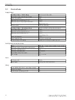
Page 92: ... 18 VA Power failure backup Min 50 ms at rated load Output voltage status display 1 green LED to display the operating state Fault Signaling Connection Relay Relay MSR relay 1 break contact isolated 2 pole terminal Maximum contact voltage with a resistive load AC 240 V Maximum switching current 5 A Maximum switching power AC 2000 VA Permissible current for contacts 5 A Test voltage VRMS 3 51 kV Fu...

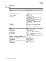
Page 93: ... index fiberglass 62 5 μm 125 μm Sensitivity 30 dBm Optical budget 10 dB 3 dB system reserve Minimum distance 1 5 km with fiberglass 3 5 m with plastic fiber 980 μm 1000 μm Minimum baud rate 0 baud Maximum baud rate 115 200 baud when using the RS232 and fiber optic interfaces at the same time 1 MBd when using fiber optic interfaces exclusively Runtimes for optical fiber operation not for RS232 Min...

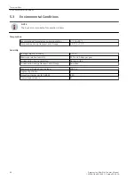
Page 94: ...ge relative humidity 75 Maximum relative humidity 95 on 30 days per year Condensation during operation Not permitted Condensation during transport and storage Permitted Maximum altitude above sea level 2000 m Degree of pollution 2 Protection class as per IEC 60529 IP 20 Overvoltage category III 5 3 Technical Data 5 3 Environmental Conditions 44 Accessories Mini Star Coupler Manual C53000 G9050 C59...

Page 95: ...n 1 minute VDE 0435 Part 303 Class III 2 5 kV direct axis voltage component 1 kV differen tial mode voltage Electrostatic discharge test IEC 60255 26 Class III EN 61000 4 2 Class III 6 kV contact discharge 8 kV air discharge both polarities 150 pF Ri 330 Ω Radiated HF field interference amplitude modulated IEC 61000 4 3 10 V m 80 MHz to 1000 MHz 80 AM 1 kHz Radiated HF field interference pulse mod...

Page 96: ...celeration horizontal axis 8 Hz to 35 Hz 1 g acceleration vertical axis Frequency sweep rate 1 octave min 1 cycle in 3 orthogonal axes Vibration and Shock Stress during Transport and Storage Oscillation Sinusoidal IEC 60068 2 6 IEC 60255 21 1 Class 2 5 Hz to 8 Hz 7 5 mm amplitude 8 Hz to 150 Hz 2 g acceleration Frequency sweep rate 1 octave min 20 cycles in 3 orthogonal axes Shock Semi sinusoidal ...

Page 97: ...Appendix A 1 Ordering Information and Accessories 48 A 2 Dimensions 49 A Accessories Mini Star Coupler Manual 47 C53000 G9050 C595 1 Edition 05 2020 ...

Page 98: ...s Description Variants Order no DIGSI cable 1 2 3 4 5 6 7 8 9 10 11 12 PC 9 pin socket and protection device 7 X V 5 1 0 0 2 25 pin plug length 3 m PC 9 pin socket and protection device 4 9 pin plug length 3 m PC 25 pin socket and protection device 5 9 pin plug length 3 m RS232 RS485 converter 25 pin plug and protection device single wire Ring cable protection length 1 m 7 Plug adapter 9 pin socke...

Page 99: ...Dimensions dw_dimensions_mini starcoupler_7XV5450_big 1 en_US Figure A 1 Dimensions in mm A 2 Appendix A 2 Dimensions Accessories Mini Star Coupler Manual 49 C53000 G9050 C595 1 Edition 05 2020 ...

Page 100: ...50 Accessories Mini Star Coupler Manual C53000 G9050 C595 1 Edition 05 2020 ...

Reviews: