Siemens 7SR220 Argus Configuration Manual Download Page 7

7SR210 & 7SR220 Configuration Guide  

1.2 Operation 

Guide 

1.2.1 User Interface Operation 

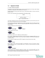
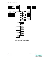
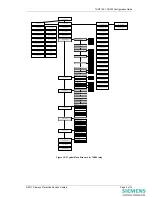
The basic menu structure flow diagram is shown in Figure 1.2-2. This diagram shows the main modes of display: 
Settings Mode, Instrument Mode, Fault Data Mode and Control Mode. 

When the relay leaves the factory all data storage areas are cleared and the settings set to default as specified in 
settings document. 

When the relay is first energised the user is presented with the following message: - 

 7SR220  

_______________________________ 

                 ENTER to CONTROL 

Figure 1.2-1 Relay Identifier Screen 


On the factory default setup the relay LCD should display the relay identifier, on each subsequent power-on the 
screen that was showing before the last power-off will be displayed. 

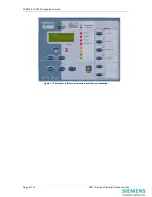
The push-buttons on the fascia are used to display and edit the relay settings via the LCD, to display and activate 
the control segment of the relay, to display the relays instrumentation and Fault data and to reset the output 
relays and LED’s. 

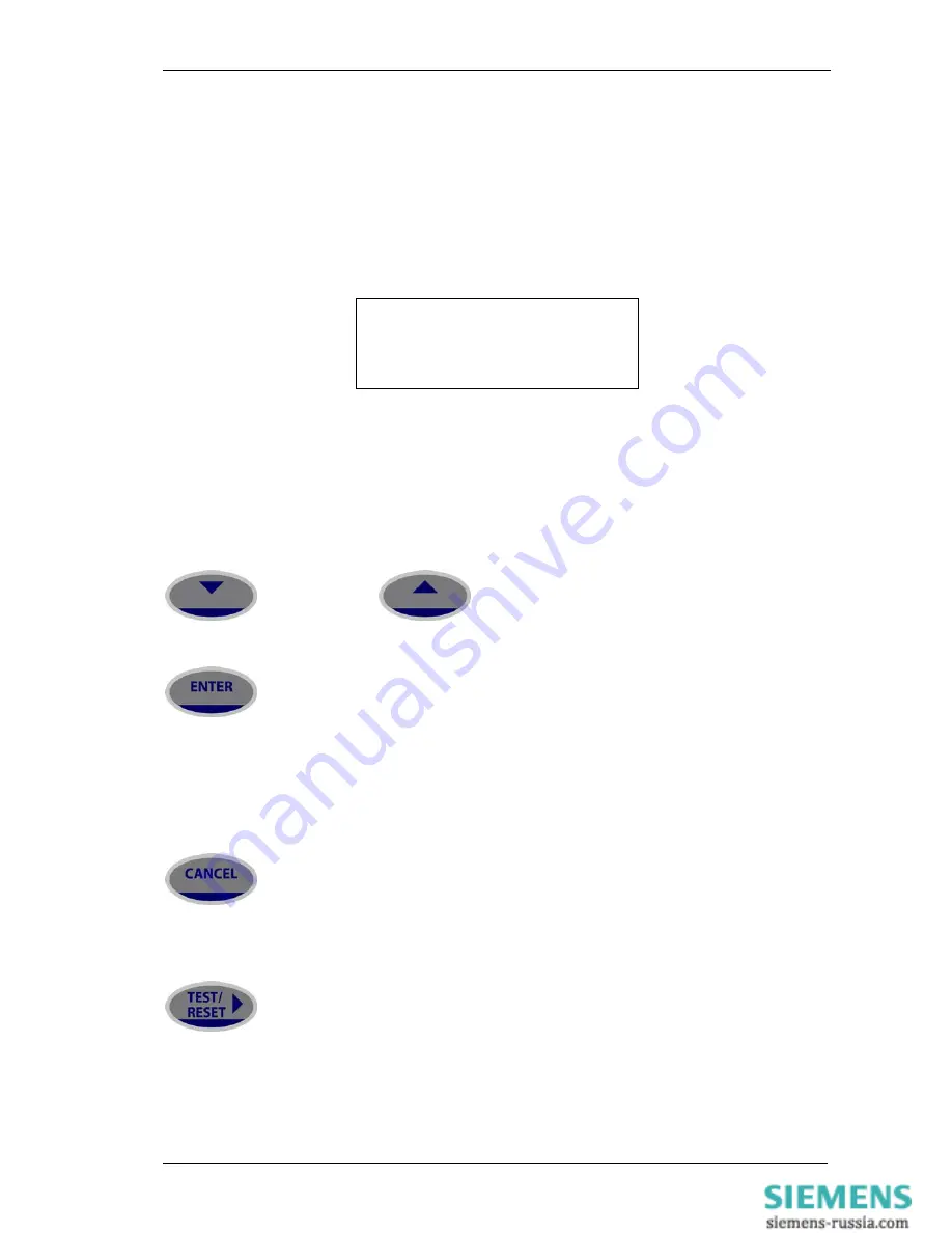
The five push-buttons have the following functions: 

 READ DOWN


 READ UP 

Used to navigate the menu structure. 

 ENTER


The ENTER push-button is used to initiate and accept setting changes. 

When a setting is displayed pressing the ENTER key will enter the edit mode, the setting will flash and can now 
be changed using the

 or 

 buttons.  When the required value is displayed the ENTER button is pressed again 

to accept the change. 

When an instrument is displayed pressing ENTER will toggle the instruments favourite screen status. 

 CANCEL


This push-button is used to return the relay display to its initial status or one level up in the menu structure.  
Pressed repeatedly will return to the Relay Identifier screen. It is also used to reject any alterations to a setting 
while in the edit mode.  

TEST/RESET 

This push-button is used to reset the fault indication on the fascia.  When on the Relay Identifier screen it also 
acts as a lamp test button, when pressed all LEDs will momentarily light up to indicate their correct operation. It is 
also moves the cursor right 

 when navigating through menus and settings. 


©2011 Siemens Protection Devices Limited  


Page 7 of 14 

Summary of Contents for 7SR220 Argus

Page 1: ...ed nor shall any model or article be reproduced from this document unless Siemens Protection Devices Limited consent While the information and guidance given in this document is believed to be correct no liability shall be accepted for any loss or damage caused by any error or omission whether such error or omission is the result of negligence or any other cause Any and all such liability is discl...

Page 2: ...7SR210 7SR220 Configuration Guide Document Release History This document is issue 2011 05 2011 05 First issue Page 2 of 14 2011 Siemens Protection Devices Limited ...

Page 3: ...ction 1 Configuring the Relay Using Reydisp Evolution 10 1 1 Physical Connection 10 1 1 1 Front USB connection 10 1 1 2 Standard rear RS485 connection 11 1 1 3 Optional rear fibre optic connection 11 1 1 4 Optional rear RS485 IRIG B connection 12 1 1 5 Optional rear RS232 IRIG B connection 12 1 1 6 Configuring Relay Data Communication 13 1 1 7 Connecting to the Relay via Reydisp Evolution 14 2011 ...

Page 4: ...Menu Structure for 7SR22 relay 8 Figure 2 1 1 USB connection to a PC 11 Figure 2 1 2 Standard rear RS485 connection to a PC 12 Figure 2 1 3 Additional Optional rear fibre optic connection to a PC 12 Figure 2 1 4 Additional Optional rear RS485 IRIG B connection to a PC 13 Figure 2 1 5 Additional Optional rear RS232 IRIG B connection to a PC 13 Figure 2 1 6 PC Comm Port Selection 14 Page 4 of 14 201...

Page 5: ... etc Fault Data Mode allows the user to view the type and data of any fault that the relay has detected Control Mode allows the user to control external plant under the relays control for example the CB if allowed via the control mode password The menus can be viewed via the LCD by pressing the access keys as below Figure 1 1 1 Menu Navigation Pressing CANCEL returns to the Identifier screen LCD C...

Page 6: ...7SR210 7SR220 Configuration Guide Figure 1 1 3 Relay Fascia Please note fascia may differ from illustration Page 6 of 14 2011 Siemens Protection Devices Limited ...

Page 7: ... output relays and LED s The five push buttons have the following functions READ DOWN READ UP Used to navigate the menu structure ENTER The ENTER push button is used to initiate and accept setting changes When a setting is displayed pressing the ENTER key will enter the edit mode the setting will flash and can now be changed using the or buttons When the required value is displayed the ENTER butto...

Page 8: ...CB WEAR CONTROL MODE CB TRAVELLING CLOSE I OPEN AR OUT OF SERVICE AR TRIP RECLOSE AR TRIP LOCKOUT E F IN HOTLINE WORKING OUT INST PROT N IN IN I OUT CONFIRM ACTION CONFIRM ACTION IN I OUT IN I OUT IN I OUT FAVOURITE METERS CURRENT METERS THERMAL METERS AUTORECLOSE METERS MAINTENANCE METERS GENERAL ALARM METERS BINARY INPUT METERS BINARY OUTPUT METERS VIRTUAL METERS MISCELLANEOUS 7SR22 ARGUS ______...

Page 9: ...NTERS I 2T CB WEAR NEUTRAL OVERVOLTAGE CONTROL MODE CB TRAVELLING CLOSE I OPEN AR OUT OF SERVICE AR TRIP RECLOSE AR TRIP LOCKOUT E F IN HOTLINE WORKING OUT INST PROT N IN IN I OUT CONFIRM ACTION CONFIRM ACTION IN I OUT IN I OUT IN I OUT FAVOURITE METERS CURRENT METERS VOLTAGE METERS FREQUENCY METERS POWER METERS ENERGY METERS THERMAL METERS AUTORECLOSE METERS MAINTENANCE METERS GENERAL ALARM METER...

Page 10: ...ftware This software requires windows 2000 service pack 4 or above or windows XP with service pack 2 or above 1 1 Physical Connection The relay can be connected to Reydisp Evolution via any of the communication ports on the relay Suitable communication Interface cable and converters are required depending which port is being used 1 1 1 Front USB connection To connect your pc locally via the front ...

Page 11: ...n Figure 2 1 3 Additional Optional rear fibre optic connection to a PC Sigma devices have a 25 pin female D connector with the following pin out Pin Function 2 Transmit Data 3 Received Data 4 Request to Send 5 Clear to Send 6 Data set ready 7 Signal Ground 8 Received Line Signal Detector 20 Data Terminal Ready 2011 Siemens Protection Devices Limited Page 11 of 14 ...

Page 12: ...le D connector 9 way D connector RS232 cross over cable or RS232 to USB converter cable IRIG B COM 3 Figure 2 1 5 Additional Optional rear RS232 IRG B connection to a PC Pin Function 1 Carrier Direct CD 2 Receive Data RXD 3 Transmit Data TXD 4 Data Terminal Ready DTR 5 Signal Ground GND 6 Data set ready DSR 7 Request to send RTS 8 Clear to Send CTS 9 Ring Indicator RI Page 12 of 14 2011 Siemens Pr...

Page 13: ...OM1 is the rear mounted RS485 port COM1 RS485 Baud Rate 75 110 150 300 600 1200 2400 4800 9600 19200 38400 19200 COM1 RS485 Parity NONE ODD EVEN EVEN COM2 USB Protocol OFF IEC60870 5 103 DNP3 0 MODBUS RTU ASCII IEC60870 5 103 COM2 is the front USB port COM2 USB Baud Rate 75 110 150 300 600 1200 2400 4800 9600 19200 38400 57600 115200 230400 460800 921600 Auto detects Auto detects baud rate via Con...

Page 14: ...red port highlighted select the Properties option and ensure the baud rate and parity match that selected in the relay Data Comms settings Select Connect to initiate the relay PC connection Figure 2 1 6 PC Comm Port Selection Via the Relay Set Address Address set the relay address 1 254 or alternatively search for connected devices using the Relay Set Address Device Map The relay can now be config...

Reviews: