7SR210 & 7SR220 Applications Guide
Page 28 of 40
©2011 Siemens Protection Devices Limited
2.15
Under/Over Frequency (81)
During normal system operation the frequency will continuously vary over a relatively small range due to the
changing generation/load balance. Excessive frequency variation may occur for:
Loss of generating capacity, or loss of mains supply (underfrequency): If the governors and other
regulating equipment cannot respond to correct the balance, a sustained underfrequency condition may
lead to a system collapse.
Loss of load – excess generation (overfrequency): The generator speeds will increase causing a
proportional frequency rise. This may be unacceptable to industrial loads, for example, where the
running speeds of synchronous motors will be affected.
In the situation where the system frequency is falling rapidly it is common practise to disconnect non-essential
loads until the generation-load balance can be restored. Usually, automatic load shedding, based on
underfrequency is implemented. Underfrequency relays are usually installed on the transformer incomers of
distribution or industrial substations as this provides a convenient position from which to monitor the busbar
frequency. Loads are disconnected from the busbar (shed) in stages until the frequency stabilises and returns to
an acceptable level.
The relay has six under/over frequency elements.
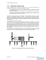
An example scheme may have the first load shedding stage set just below the nominal frequency, e.g. between
49.0 - 49.5Hz. A time delay element would be associated with this to allow for transient dips in frequency and to
provide a time for the system regulating equipment to respond. If the first load shedding stage disconnects
sufficient plant the frequency will stabilise and perhaps return to nominal. If, however, this is not sufficient then a
second load shedding stage, set at a lower frequency, will shed further loads until the overload is relieved. This
process will continue until all stages have operated. In the event of the load shedding being unsuccessful, a final
stage of underfrequency protection should be provided to totally isolate all loads before plant is damaged, e.g.
due to overfluxing.
An alternative type of load shedding scheme would be to set all underfrequency stages to about the same
frequency setting but to have different length time delays set on each stage. If after the first stage is shed the
frequency doesn’t recover then subsequent stages will shed after longer time delays have elapsed.
Generator
Network
Incomer
G59
300/5
STAGE 1: Least important
STAGE 2
STAGE 3
STAGE 4
Essential
Load
STAGE 5
STAGE 6
6
1
2
5
5
3
2
4
4
Figure 2.15-1 Load Shedding Scheme Using Under-Frequency Elements


