7SG11 Argus Technical Reference
©2013 Siemens Protection Devices Limited
P20007 Page 62 of 71
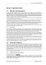
Reyrolle protection relay
Trip contacts
Status input
-ve
Circuit breaker
Open position
+ve
Auxiliary contacts
Trip coil
P300005 Application Diagrams / TCS H5
Trip Link
Rd
Rs
Auxilliary
Status
Rs
Rd
I
TRIP COIL
I
TRIP COIL
I
TC max
Note1
Voltage
Voltage
CB Open
CB Closed
CB Closed
110/125 V
48 V
2K7
2K7
< 20 ma
< 35 ma
< 55ma
110/125 V
110/125 V
4K7
4K7
< 2.5 ma
< 5 ma
< 35 ma
220/250 V
220/250 V
10K
10K
< 2.5 ma
< 5 ma
< 30 ma
Note 1:- Worst case current - Short circuit applied across Status input with CB Closed and max Auxilliary Voltage.
Resistors must be at least 18 Watt rated and connected using crimped connections as under worst case they will
run hot.
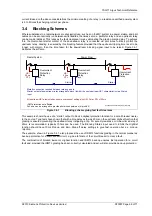
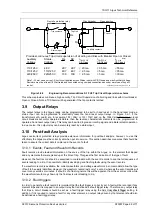
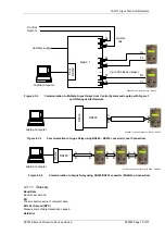
Provides continuous Trip circuit supervision of all wiring and links with Breaker Open or Closed.
Figure 3.8-2
Engineering Recommendations S.15 H5 Trip Circuit Supervision scheme
This scheme provides continuous, high security, Trip Circuit Supervision of all wiring and links with circuit breaker
Open or Closed. Note a TCS Alarm will be generated if the trip contact is latched.
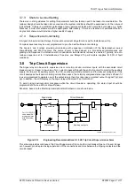
3.9 Output Relays
The output relays in the Argus range can be programmed to be self or hand reset. In the hand reset mode, a
status input can be programmed to electrically reset the hand reset output relays. In Figure 3.2-1, if the
transformers at A and B are, for example, 132 / 33kV or 132 / 11kV and, on the 132kV side there are no local
circuit breakers but motor operated isolators, then the reverse characteristic elements can be programmed to
operate a hand reset output relay. This relay can be wired to give an intertrip signal and initiate isolator operation.
In due course, this output relay can be remotely reset by a status input.
3.10 Post-fault Analysis
Argus overcurrent protection relays provide extensive information for post-fault analysis; however, to use this
effectively the Argus must be correctly set when put into service. This section describes measures that should be
taken to ensure the correct data is captured in the event of a fault.
3.10.1 Events, Fault and Waveform Records
Fault records provide textual information on the source of the trip within the Argus, i.e. the element that tripped
and any elements that were picked up at the time of trip. This gives the first indication of the type of fault.
However, the fault record should be examined in coordination with the event records to see the full sequence of
events leading to a trip. It is possible to identify developing and flashing faults using the event records.
If a waveform record is available, the current waveforms (and voltage waveforms in some models) allow the type
of fault to be easily identified. However, the waveform record lasts only 1 second, whereas the event records will
cover many seconds or minutes. If a fault is of a flashing nature this will be apparent from the event records, while
the waveform record may show only the final overcurrent leading to trip.
3.10.2 Fault triggers
In order to generate a fault record it is important that the fault trigger is correctly set. A fault will be recorded if any
element trips and it is mapped to an output relay that is defined as a fault trigger relay. Therefore, any output relay
that trips a circuit breaker should be set as a fault trigger relay using the
Data Storage:
Fault Trigger
setting. In
addition, if it is required to record a fault for any other element, an output relay driven by that element should also
be defined as a fault trigger relay.


