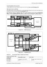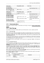
7SG11 Argus Technical Reference
©2013 Siemens Protection Devices Limited
P20007 Page 51 of 71
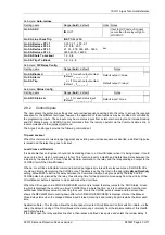
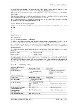
The standing number of FOC trips and the FOC Alarm level are displayed in the
Instruments:
Freq Op Counter
. The
FOC counter can be reset using
CB Maintenance:
Freq Op Counter Reset
, when viewing the counter’s instrument, or by
raising a status input mapped to
Status Config.:
FOC Reset
.
Table 2-27
Circuit Breaker Maintenance Settings
Sub-menu:
CB Maintenance
Setting name
Range (
bold
= default)
Units Notes
Trip Counter Reset
NO
, YES
Trip Counter Alarm
OFF
, 1, 2…999
Argus 4 and Argus 6 only.
Trip Counter Reset
NO
, YES
Trip Counter Alarm.
OFF
, 1, 2…999
Freq Op Counter Reset.
NO
, YES
Freq Op Counter Alarm
OFF
, 1, 2…999
Argus 4 and Argus 6 only.
I² Reset
NO
, YES
I² Alarm
OFF
, 10, 11…100, 110…
20000, 21000…100000
MA
2
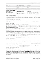
Sub-menu:
O/P Relay Config.
Setting name
Range (
bold
= default)
Units Notes
Gn Trip Alarm
Argus 4 and Argus 6 only.
Gn Counter Alarm
Gn I² Alarm
Gn FOC Alarm
_, 1 for each output contact
(default:
_ _ _ _ _ _ _ _ _ _ _
)
Argus 4 and Argus 6 only.
Sub-menu:
Status Config.
Setting name
Range (
bold
= default)
Units Notes
Gn Trip Counter Reset
Argus 4 and Argus 6 only.
Gn Counter Reset
Gn FOC Reset
Argus 4 and Argus 6 only.
Gn I
2
Update
_, 1 for each status input
(default:
_ _ _ _ _ _ _ _ _
)
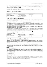
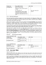
2.14.2 Output Relay Test
The output relay test allows the Argus to simulate a particular element operation, e.g. P/F Highset 1, and energise
all output contacts that would normally be energised from that element output. This is useful during
commissioning/routine tests, so that wiring and operational checks can be performed without the need for
secondary injection.
The required element is selected from the list available in the
CB Maintenance:
O/P Relay Test
setting. Scroll to that
setting, press ENTER, select the required element name using the up or down keys, press ENTER to select, a
confirmation screen ‘ ** O/P Test ** Are You Sure ? N ‘ will be shown, confirm by using the up or down key to
change to ‘
Y
‘ and press ENTER. An active countdown timer will then be shown in a ‘ ** TRIP TEST IN** , ** xx
SECONDS ** ‘ screen. The counter decrements from 10 seconds to zero, then all output relays mapped to that
element are energised for 100ms, then a message TRIP TEST FINISHED is briefly displayed.
The time delay before output relay energisation allows personnel to leave the vicinity of the circuit breaker before
a live system trip test is performed.
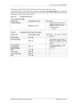
Table 2-28
Output Relay Test Setting
Sub-menu:
CB Maintenance
Setting name
Range (
bold
= default)
Units Notes


